AirGradient ONE Air Quality Monitor (I-9PSL-DE PCB Version 9+) Assembly Instructions
AirGradient ONE Air Quality Monitor (I-9PSL-DE PCB Version 9+) Assembly Instructions
Introduction
Welcome to your AirGradient ONE!
This kit is designed to be easy for anyone to assemble with no electronics background or soldering experience required. Everything you need comes neatly packed in the box, including a Torx T6 screwdriver.
From opening the box to a fully functioning air quality monitor takes roughly 15 minutes.
The PM sensor is pre-mounted, and firmware is pre-installed, so your device will automatically update itself once it connects to Wi-Fi.
If you’re new to AirGradient or air quality monitoring, you’re in the right place. This guide walks you step-by-step through the assembly, connection, and troubleshooting process with pictures and video links along the way.
If you have a different version please find all of our build instructions in this overview. The version number is printed on the PCB under the AirGradient logo. PCB layout references including CAD, Gerber files and more technical details can be found in the same overview.
Video Tutorial
In case you have any problems after completing the build, you can check the troubleshooting section.
Equipment Required
For assembly only a Torx (T6) screwdriver is required. This is included in the kit. No soldering is required.
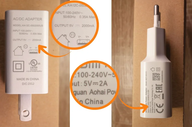
For powering the device, you’ll need a 5V 2A power adapter. This is not included in the kit.
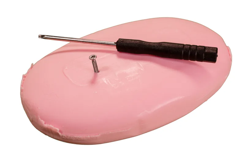
Soap for lubricating screws (optional).
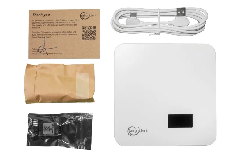
Components
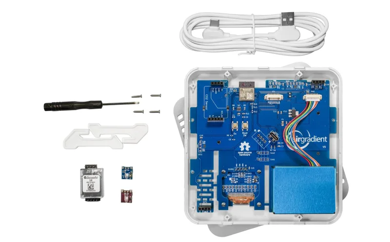
Below is the list of components that you will receive with the kit:
| Component | Description |
|---|---|
| AirGradient ONE PCB v9 | with ESP32-C3-MINI, OLED Display, connectors and pin sockets. |
| Plantower PMS5003 PM Sensor | pre-mounted particulate matter (PM) sensor with cable. |
| Senseair S8/S88 CO2 Sensor | with pre-soldered pins |
| SHT4x Temperature and Humidity Sensor Module | with pre-soldered pins |
| SGP41 TVOC / NOx Sensor Module | with pre-soldered pins |
| USB-C Cable | 90-degree head (USB A to USB C) |
| Enclosure | UV-resistant injection molded ASA plastic |
| Stands | UV-resistant injection molded ASA plastic |
| Screws for Enclosure | 4x M1.8x10 (Torx T6) |
Assembly Instructions
We recommend you assemble your monitor in the following order:
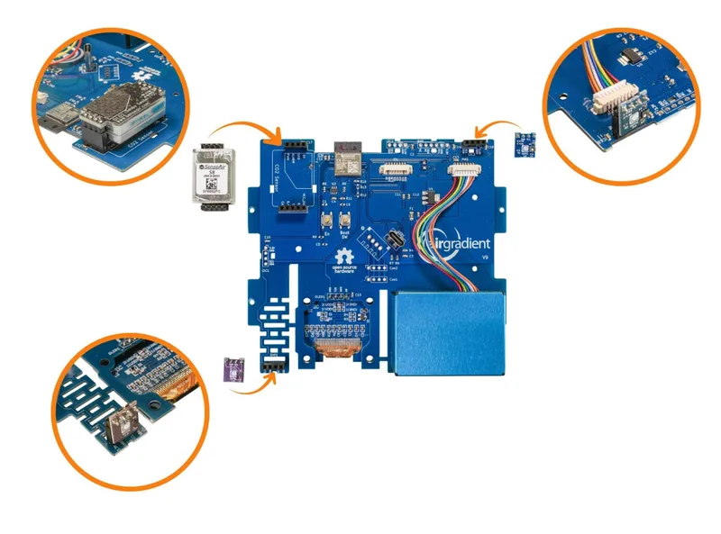
1. Install the SHT4x Module (Temperature and Humidity Sensor)
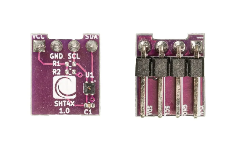
Install the SHT4x module as per the picture below. It should be inserted in the slot at the bottom left of the board labelled “SHT1”. The AirGradient logo should face outward.
Note: The SGP41 (TVOC) module looks very similar to the SHT4x Module (Temperature and Humidity Sensor). Please pay close attention to ensure you don’t mix up the modules.
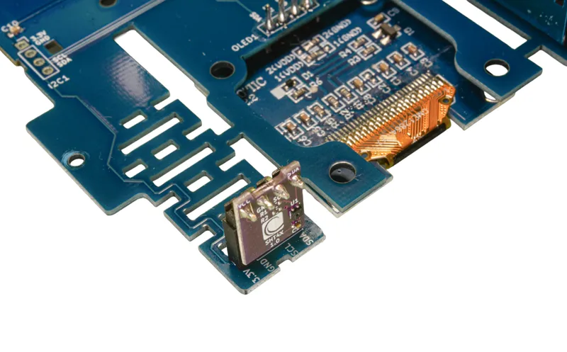
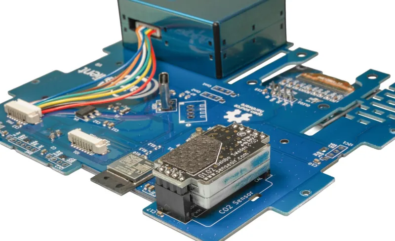
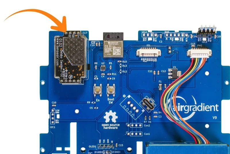
2. Senseair S8/S88 Module (CO2 Sensor)
Next, insert the CO2 Module in the pin sockets labelled “CO2 Sensor”. Make sure that the orientation is correct and all pins slide into the sockets.
By default, the CO2 sensor uses a 7-day automatic baseline calibration and thus needs a few days to become accurate.
Please note that some monitors may come with an S8 module, and some with an S88. These are functionally the same and should be placed in the same way.
3. SGP41 TVOC / NOx Module
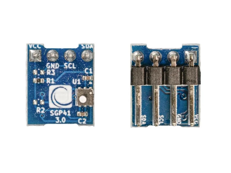
Mount the TVOC / NOx sensor in the slot in the top-left corner labelled “I2C3”.
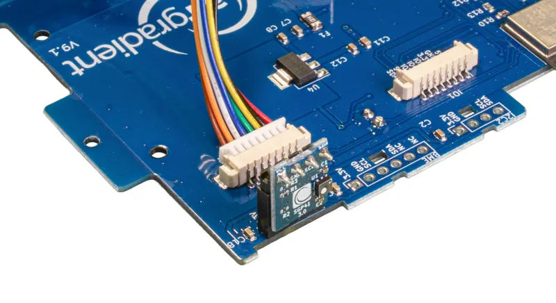
Please make sure you mount the module in the correct orientation. The sensor needs to face outwards.
Again, please ensure that the SGP41 and SHT4x modules are in the correct locations on the board (pictured above) and that they are both orientated with the logo facing outwards. If these sensors are mixed up, the device will still work, but the readings from these sensors may be inaccurate.
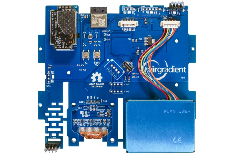
The fully assembled PCB will look like below:
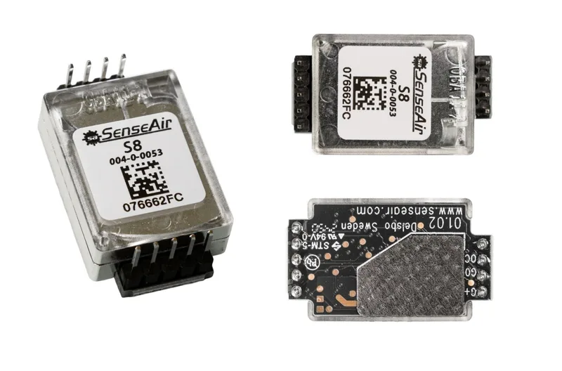
4. Take Note of Your PM Module Serial Number
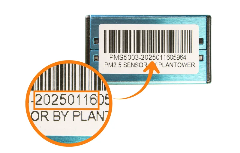
We have developed a range of batch-corrections for the PM sensors used in our monitors which help to improve accuracy and precision. To apply these batch corrections, you will need to know the first eight digits of the PM sensor's serial number.
To find the serial number, please look at the blue PM module from the bottom of the board. Each sensor will have a sticker like the image above. For further information on the batch corrections, please refer to this article.
To avoid needing to open the monitor at a later date, please note down or take a photo of this number.
5. Testing the PCB And Putting It Into The Enclosure
You can now power on the device by plugging in the USB cable. After a few seconds, you should see the display light up. The power adapter is not included in the kit. Please use a standard 5V, 2A power supply.
You will likely have one of these lying around your house from a smartphone or another device.
Please note that if the device does not turn on - or if you notice unexpected behaviour like the device restarting randomly - you may need to use a different USB adapter.
Connecting Your Device
To connect the device to Wi-Fi and register it on the AirGradient dashboard, follow the onboarding process.
If you don’t want to use the AirGradient Dashboard use the instructions here: WiFi Connection Instructions. (Video Instructions: Android - iOS)
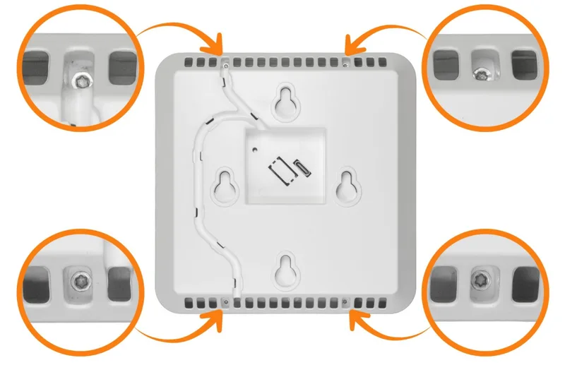
If everything works, place the PCB assembly inside the enclosure. The PCB does not need screws as it is held firmly in place by the enclosure. Then close the enclosure using the four long screws provided, inserted through the side vents.
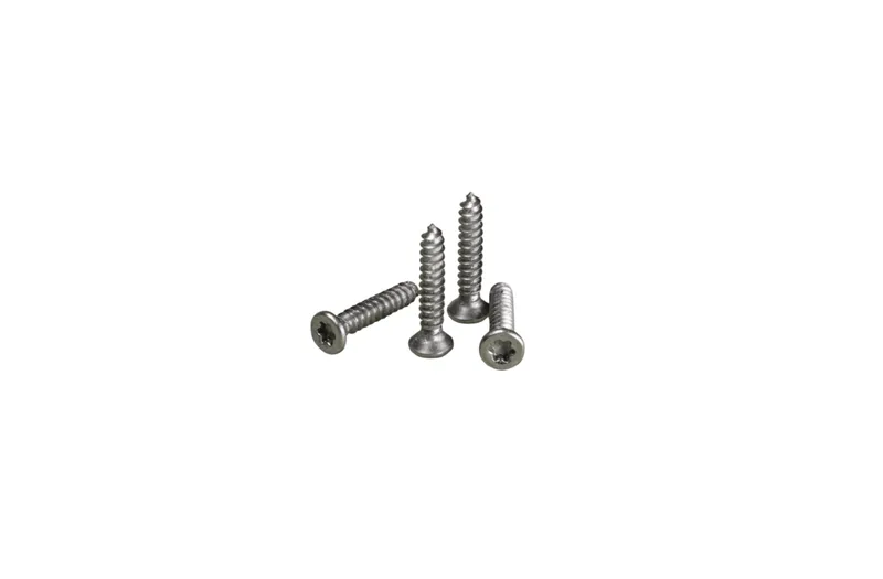
The enclosure screws go into the four ventilation vents around the back of the device:
Please note that the mini screwdriver enclosed with the kit might not have enough torque to screw these screws all the way in. In that case, please use a larger T6 screwdriver, or you can also put some oil/soap on the screws to make them go in easier.
Please also be careful not to force the screws in, as this can lead to them getting stuck in the case and may make the device hard to open for maintenance.
Power Supply
Please use a standard 5V, 2A power adapter. Using lower-rated power adapters can cause issues. If you notice issues like a distorted screen or sensors dropping out, this is likely due to the power supply being used.
Firmware Flashing Through The Browser
The device comes with pre-installed firmware so it’s ready to run, however, if you want to perform manual firmware updates you do so using this page: AirGradient Firmware Versions
Home Assistant and Local Server
The firmware has native Home Assistant support and should get auto discovered. Additionally, there is a local server exposed that can be used to read data directly from the monitor in a local network (and set configuration parameters).
Troubleshooting
Here is a list of common issues and how to resolve them:
| Behavior | Potential Reason | Fix |
|---|---|---|
| Incorrect Temp/Humidity values. | TVOC or Temp/RH modules mounted the wrong way. | Make sure that the small modules for TVOC and Temperature/Humidity measurement are mounted correctly with the small AirGradient logo facing outwards. |
| Enclosure screws are hard to screw in with a small screwdriver. | Put some soap on the screws or use a larger T6 screwdriver. | |
| PM or CO2 shows -1 or -3 on the display | Sensor module not connected properly. | Make sure that the sensors are plugged in correctly and that the cable is firmly connected. |
| TVOC shows 0 | The sensor module has not warmed up yet. | The TVOC module needs around 1-2 minutes to warm up before it shows values. |
| NOx shows 0 | NOx module not very sensitive. | In most cases NOx is around 0 or 1. Only in cases of very high concentrations will it rise above those values. |
| PM shows 0 | See our calibration guide. |
Placement Instructions
For accurate readings and optimal performance, it’s crucial to place the device correctly.
Please follow the detailed placement instructions to ensure your monitor is securely installed and functioning properly.
CC BY-SA 4.0 Attribution-ShareAlike 4.0 International
This work is licensed under CC BY-SA 4.0.
This license requires that reusers give credit to the creator. If you remix, transform, or build upon the material, you must distribute your contributions under the same license as the original.
Copyright AirGradient Co. Ltd.