The AirGradient Open Air Outdoor Air Quality Monitor (Presoldered-Version, PCB Version 1.1)
The AirGradient Open Air Outdoor Air Quality Monitor (Presoldered-Version, PCB Version 1.1)
Introduction
These build instructions cover the pre-soldered version of the AirGradient Open Air Outdoor monitor kit for PCB version 1.1. If you have a different version please find your correct build instructions in this overview. The version number is printed on the PCB.
The AirGradient Open Air Outdoor Monitor measures PM2.5, temperature and humidity. These measures can be sent to a server (e.g. the AirGradient dashboard and map or any other cloud backend) for data logging. The monitor is fully open-hardware / open-source. Schematics, Ki-Cad files, enclosure step files etc. are all freely available.
You can purchase the kit with all components from our Online Store which includes the plastic injected enclosure that looks really nice. We ship world-wide.
Video Tutorial
(Please note that we now supply four screws with the ideal length and no longer need the four replacement screws mentioned in the video).
Skills And Equipment Required
For this project you should be familiar with the following:
| Skill | Description |
|---|---|
| Computer | A Linux, Mac, or Windows computer with the Arduino IDE installed to flash the software onto the microcontroller. You can also flash the software directly from the browser (recommended). |
| Screwdriver | You need a torx (T6) screwdriver which is included in the kit. |
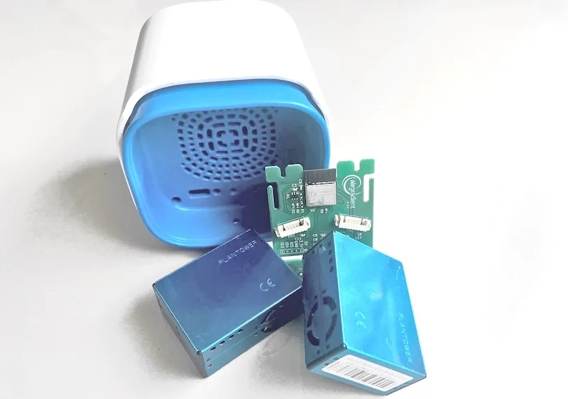
Components
Below is the list of components that you will receive with the pre-soldered kit:
| Component | Details |
|---|---|
| AirGradient Open Air PCB | with ESP-32-C3 |
| 2x Plantower PMS5003T | PM Sensor |
| 2x JST 8 cross-over cable | for connecting PM sensors |
| USB-C cable | 4 meter long (for flashing and power) |
| Enclosure | UV-resistant injection molded ASA plastic |
| 4x Screws for enclosure | M1.8x11 (Torx T6) |
| Screwdriver | Torx T6 |
Technical Documentation
Technical documentation including schematics, BOM, KiCad files etc. can be found here.
Assembly
The assembly of the unit is very simple as you just need to connect the two PM sensor modules to the PCB and then fit all parts into the enclosure and screw the enclosure parts together.
We recommend you start in the following order:
Connect the PM Cables
First connect the PM cable to the PM sensor. Make sure you put the cable into the PM sensor in the right way. Then feed the cable through the small slots on the PCB and connect the cable to the PCB. You need to press the cables into the PM sensor and connector tightly. Please ensure that the cable is fully plugged in on both ends.
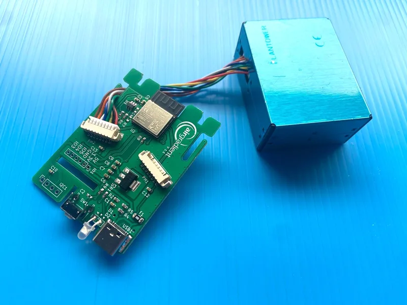
Then repeat the same thing for the second PM module.
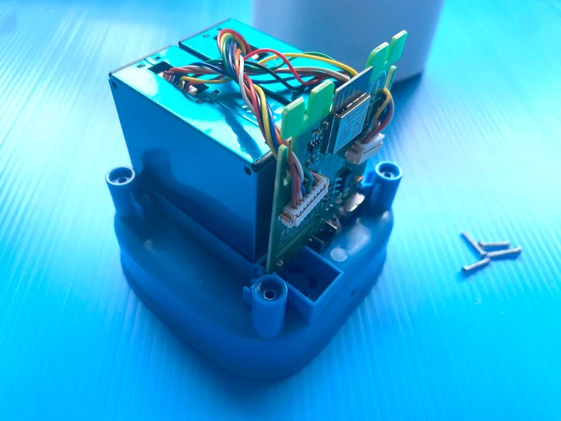
Placement of the parts inside the enclosure
After you have connected both PM modules, place the PCB, PM modules into the blue bottom plastic part of the enclosure.
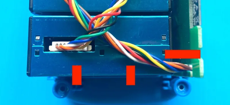
Please note the following: Twist the cable around 3 times and put the PM modules cross over from the cable exit on the PCB.
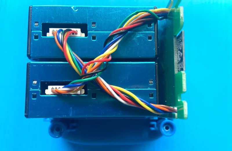
It is important that the cables are not squeezed from the plastic parts of the enclosure. So you should avoid that the cables are on the areas marked red in below image. Have a look at the inside of the white top part of the enclosure to see which parts might press onto the cable.
Closing the enclosure
After you have made sure that the cables are aligned correctly, the PCB is 100% upright and that all parts are fitted in correctly, carefully slide the top part onto the assembly. As soon as you feel there is some resistance from components inside the enclosure, do not force it but lift up the top part and check again if the PCB is upright and the cables not interfere with the pastic rifts.
Once the two parts slide together smoothly, turn the complete assembly around and use the four screws to put it together.
Power Supply
The power supply is not included in the kit. Please get a standard 5v, 2A power supply. If you use the power supply outdoors, please make sure it is suitable for outdoor use and does not pose a safety risk.
Software
The kit already comes with the software flashed to connect it to the AirGradient dashboard and map. So in case you do not want to change the firmware and connect it to a different server, you can skip this software part and continue with connecting to the Dashboard and Map part.
Direct Flashing Through The Browser
| Firmware | |
|---|---|
|
Flashing InstructionsImportant. Please follow these steps for flashing only. If you only want to see debug messages and logs of the monitor see the instructions for logging:
Logging InstructionsFollow below to see debug messages and logs of the monitor:
Now you can see the debug messages and also identify the serial number. |
|
Flashing With The Arduino Software
If you want to make changes to the code, you can do so with the Arduino software by following below steps.
a) Install the Arduino Software on your computer. Do not use the web version but download and install the version for Linux, Mac, or Windows. This software is used to transfer the code to the microprocessor (and make adjustments to the code).
b) Enable the ESP32 C3 board. You need to enable the MCU in the Arduino IDE by following these steps:
- Start Arduino and open the Preferences window.
- Enter https://raw.githubusercontent.com/espressif/arduino-esp32/gh-pages/package_esp32_dev_index.json into Additional Board Manager URLs field.
- Open Boards Manager from Tools > Board menu and find the ESP32 platform.
- Select the latest version you need from a drop-down box.
- Click the install button.
- Select the Lolin C3 Mini board from Tools > Board menu after installation.
Flashing Of The AirGradient Firmware
Once you have the Arduino Software setup for the C3 Mini, you can flash it with the AirGradient firmware.
| Step | Description |
|---|---|
| 1 | Go to Tools, Manage Libraries, and then search for AirGradient and install the AirGradient library. Make sure you install the Arduino AirGradient library version 2.4.3 or higher. |
| 2 | Once it is installed, go to File, Example, AirGradient and select the DIY_OUTDOOR_C3 code |
| 3 | Read the instructions on top of the example code |
| 4 | Then edit/flash this code |
BOOT Error During Flashing
In case you get an error called "Failed to initialize. Try resetting your device or holding the BOOT button while clicking INSTALL" during the flashing, you need to put the board into a special boot mode. To do this please follow below steps:
- Push the button labelled on the PCB and keep it pushed. This is also the button behind the small hole next to the USB connector at the bottom of the enclosure. So if you don't want to open the enclosure you can also press it with a small pin through the enclosure.
- Plug in the USB C cable
- Release the button. If you do not do this, the board will not get into the flash mode.
- Press the blue button above to flash
- Select the serial port your monitor is connected to. It is typically called “USB JTAG / Serial Debug”
- Follow the instructions for flashing. In case you want to delete previously saved WiFi passwords on the device, check the box 'Erase the Device'.
- After the flashing is complete, restart the monitor by unplugging the USB C cable (and plugging it back in)
PMS Library Patching
We use the PMS5003T version for PM sensor which includes an integrated temperature and humidity sensor. If you use the Arduino Sketch from the AirGradient Arduino library you need to patch the PMS library to get these values.
Please follow these steps to patch the PMS library.
AirGradient Dashboard & Map
The easiest way to start using AirGradient Dashboard and Map with your monitor is our onboarding wizard:
It will first guide you through the account creation (or login if you already have an AirGradient account). Then you will be able to set up your place. A place is where you can connect several monitors to. For example your house, school or office. Each place has its own dashboard.
Once you have your account and place setup, you will be able to connect your monitor to the WiFi and add it to your place’s dashboard by following the wizard instructions.
When the monitor is connected and "Share data with the AirGradient API, AirGradient Map and 3rd parties" is activated, your monitor will appear on the AirGradient Map.
In case you only want to connect the WiFi or have some problems, please check out our knowledge base articles.
AirGradient Dashboard & Map
Once you have assembled the kit, you can power it on by just connecting the USB C cable.
STEP 1: Conecting the monitor to WiFi
Here are video instructions on how to connect the monitor to WiFi or alternatively follow the text instructions below the video:
IMPORTANT:
Note down exactly the serial number displayed in the hotspot name. You will need this later on to register the monitor on the dashboard. Also, you need to connect the monitor within 90 seconds, otherwise the hotspot will disappear and you need to re-power the monitor and start over.
Connect with your phone to it and if prompted for a password use "cleanair". Once the Wifi Manager opens, click on "Configure Wifi" and enter your Wifi network credentials. It will then connect to Wifi and start sending the air quality data.
If you have the serial debug on, you will see the logs with the requests going out. If the monitor's serial number has not been setup by the server, you will receive a 4xx response. Once the server knows about the monitor (step 2), it will receive a 200 response.
STEP 2: Setting up the AirGradient dashboard / map
Here are video instructions on how to connect the monitor or alternatively follow the text instructions below the video:
Once you have connected the monitor to your WiFi, head over to our onboarding website at:
https://app.airgradient.com/onboarding/welcome
It will first guide you through the account creation (or login if you already have an AirGradient account). Then you can setup a place. A place is where you can connect several monitors to. For example your house, school or office. Each place has its own dashboard.
Once you have your account and place setup, you can add a monitor to your place's dashboard. This is done on the step called "Setup your Monitor". Here chose the tab "Setup Open Air Outdoor Monitor".
If you have already setup the WiFi you can immediately go to step 2. Here you need to enter the following information:
Sensor Number
This is the serial number of the monitor that you have noted down during the WiFi setup (see above). Enter this number here.
Please make sure that you use it in lower case only and also do not use "AG-" which is not part of the serial number. So if for example, the wifi hotspot showed "AG-625bf2", then "625bf2" is the serial number.
Additionaly, you can also see it on the serial debug when it is connected to the WiFi and starts sending data.
In the serial debug you will find lines like:
"....airgradient.com/sensors/airgradient:SERIAL_NR/measures " where "SERIAL_NR" would stand for the actual chip id of the monitor.
Place
Under Place just select your place name that you setup. All monitors of one place will be on the same dashboard.
Dashboard Name of Location
Here enter the location of the monitor.
Public
We encourage you share your outdoor data on our map (and also OpenAQ). In case you do not want to share your air quality data, please disable this.
Public Name of Location
Enter the name of the monitor as it should appear on the map.
Latitude and Longitude
Enter the latitude and longitude of the outdoor location separated by a comma. In regard to privacy, please keep in mind that we show exact location on our map, so you might want to slightly move the location. You can find the latitude and longitude by searching for the location on Google Maps, then right-click on the location on Google Maps and you will see the latitude, longitude. Copy and paste this into above field.
Add Sensor to Dashboard
Once you filled in all the information, please click on the red "Add" button. This will add your monitor and location to the dashboard. Then you can go to Step 3 and either add another monitor or go to the dashboard.
Map
Once the monitor sends data and is set to public, you can see the data on your dashboard as well as on the AirGradient Map.
Finding the Serial number
In case you did not note down the serial number, you can do the following:
- Connect your monitor with your computer
- Click on the blue button for flashing the monitor in the software section.
- Select the serial port your monitor is connected to. It is typically called "USB JTAG / Serial Debug"
- Click on "Logs & Console"
- Click on "Reset Device" to reboot the monitor
- Now you should see a line "starting ...Serial Number: xxx" with xxx being your serial number
CC BY-SA 4.0 Attribution-ShareAlike 4.0 International
This work is licensed under CC BY-SA 4.0.
This license requires that reusers give credit to the creator. If you remix, transform, or build upon the material, you must distribute your contributions under the same license as the original.
Copyright AirGradient Co. Ltd.