Knowledge Base
The AirGradient DIY Outdoor Air Quality Monitor
Table of Contents
- Introduction
- Skills and Equipment
- Components
- Schematics
- PCBs
- Software
- Soldering the Components
- 3D Enclosure
- Dashboard
- License
Introduction
These build instructions cover the ESP8266 based version of the AirGradient Open Air Outdoor monitor PCB version 0.4. If you have bought the kit from our shop with the ESP32-C3 based chip and PCB version > 1.0, please find your correct build instructions in this overview. The version number is printed on the PCB.
The AirGradient Outdoor DIY monitor measures PM2.5, temperature and humidity. It can be configured with one or two PM modules for enhanced accuracy and lifetime. It offers easy extensability, e.g. adding a TVOC module.
You can completely build the monitor on your own with the instructions below and open-source code or, optionally you can go to our online shop and pre-order it as a pre-soldered kit that includes all components.
Skills And Equipment Required
For this project you should be familiar with the following:
| Skill | Description |
|---|---|
| Soldering skills | Most of the components we use need soldering. The PMS connectors are small and therefore a bit difficult to solder but these connectors are optional and the monitor can also be built without them. |
| Soldering Iron & Solder | To solder the component pins and cables. |
| Computer | A Linux, Mac, or Windows computer with the Arduino IDE installed to flash the software onto the D1 Mini. You can also flash the software directly from the browser. |
| USB-C Data Cable | A USB-C cable for flashing the microcontroller and later powering it. |
In case you are unfamiliar with soldering or want to get the monitoring working as quickly as possible, we also have pre-soldered kits available, which can be assembled in just a few minutes with no soldering needed.
Components
Below is the list of components that you need to source, with a purchase link and typical price ranges. Please note we have no association with the linked sellers and only provide the links as an example of the components, not an endorsement of a seller or a guarantee of the linked product quality.
| Component | Approx. Price |
|---|---|
| Wemos D1 Mini v4 USB-C | USD 4 - 6 |
| USB C Plug | < USD 1 |
| Plantower PMS5003T PM Sensor | USD 15 - 20 |
| 10kΩ Resistor | < USD 1 |
| 200Ω Resistor | < USD 1 |
| Button | < USD 1 |
| 3mm LED red | < USD 1 |
| Short 8Pin PMS Cable | USD 2 |
| USB-C Connector 6 Pin | < USD 1 |
| JST Connector 1.25mm 8 Pin for PMS | < USD 1 |
| Screws | Enclosure: M1.7x10 (Philips/Torx M6). |
| USB-C Cable | USD 3 - 6 |
| PCB | See below on how to make a PCB |
| Enclosure | See below on how to 3D print the enclosure |
You can also purchase the kit with all required components from our Online Store and be sure that everything fits. We ship world-wide.
comment: <> (
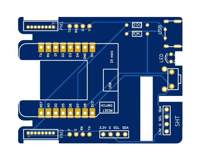
Schematics
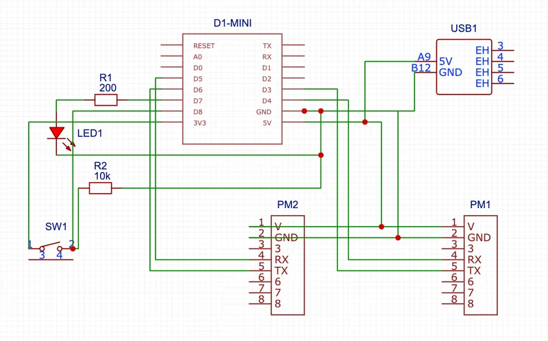
Make Your Own PCBs
In case you want to make your own PCB you can use our Gerber files.
Direct Flashing Through The Browser
You can either manually flash the code through the Arduino software or use the more simple buttons below.
Connect the D1 Mini to your computer through a data-capable cable and press the button below. Make sure you use the Chrome or Edge browsers on your computer for this to work.
| DIY Outdoor Firmware | |
|---|---|
|
|
|
Once the code is flashed, it will open a hotspot for 60 seconds to which you can connect and then set your Wi-Fi credentials. By default it will connect to the AirGradient Dashboard. If you want to use another endpoint you can change the code with the manual flashing method below.
If you flash with the method above, you can skip the next section and continue at the section "Soldering the Components".
Manual Flashing With The Arduino Software
The above direct flashing is the easiest way to get the firmware onto the D1 Mini but if you want to make changes to the code, you can also flash the code through the Arduino software environment. All software for the AirGradient DIY sensor is open source and thus you can make any changes you’d like.
Please read the following blog post on how to install the Arduino software, set up the D1 Mini board and the AirGradient Arduino library.
AirGradient Arduino Software Setup Instructions
Flashing Of The AirGradient Firmware
Once you have the Arduino Software setup for the D1 Mini, you can flash it with the AirGradient firmware.
| Step | Description |
|---|---|
| 1 | Go to Tools, Manage Libraries, and then search for AirGradient and install the AirGradient library. |
| 2 | Once it is installed, go to File, Example, AirGradient and select the DIY_OUTDOOR code |
| 3 | Read the instructions on top of the example code and install the additional libraries |
| 4 | Then flash this code the same way you flashed the BLINK example |
| 5 | Once you have successfully uploaded the code you can continue building the hardware |
Soldering The Components
Now that you have the firmware flashed, you can solder the components onto the PCB. Make sure you solder the pins in the correct direction.
We recommend you start in the following order:
D1 Mini Soldering
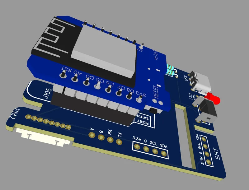
We recommend to solder the D1 mini with pin sockets so that it is easier to replace components or troubleshoot if something does not work.
Important: If you solder the D1 directly on the board, leave enough space between the D1 and the PCB so that you can plug in the USB cable. The button might block the USB cable.
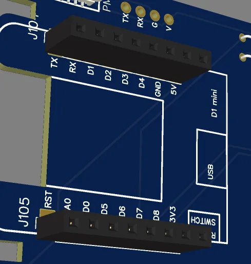
First solder the female pin headers onto the PCB where it says: "D1 mini".
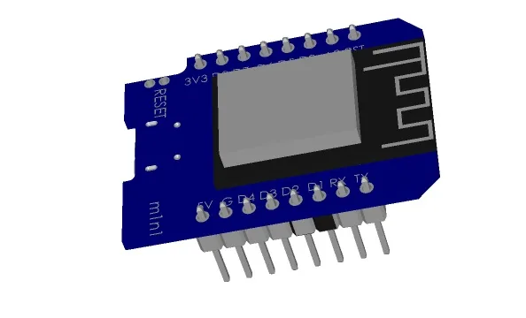
Then solder the male pins onto the D1 Mini.
Then you can put the D1 Mini onto the PCB. Make sure that the orientation is correct and that all pins go into the socket.
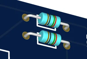
Soldering The Resistors
Solder the two resistors onto the PCB.
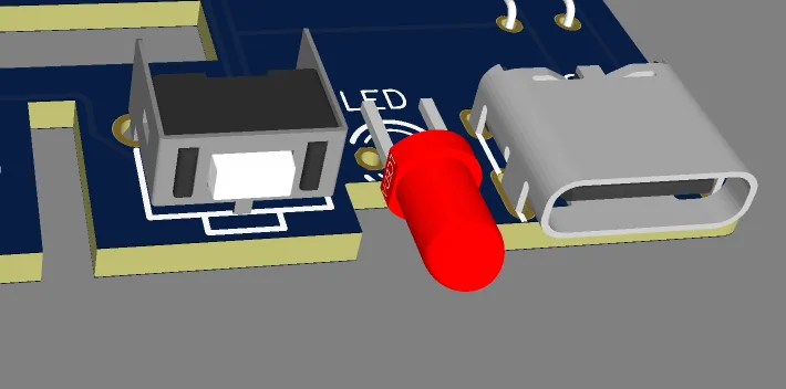
Soldering The USB C plug, Button And LED
Then solder the USB C plug, LED and button onto the PCB. Observe the marking on the PCB to ensure you solder the LED in the correct way. The flat area of the LED need to match the line on the PCB.
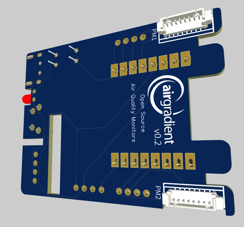
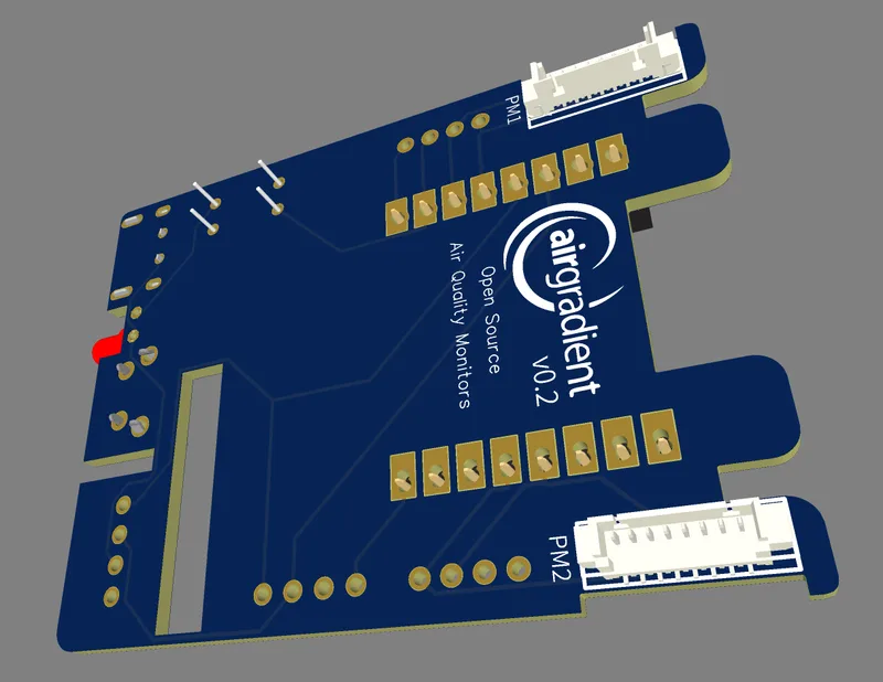
Soldering The PMS5003T Connector
IMPORTANT!
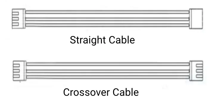
There are two types of cables. Straight cables or cross-over cables. Depending on which cable you use, you need to solder the connector in a specific direction.
In both cases, the connector is soldered on the opposite side of the PCB.
How can you identify which cable you use? Lay the cable on a flat surface and compare the connectors:
Depending on the cable type please solder the connector in the below way:
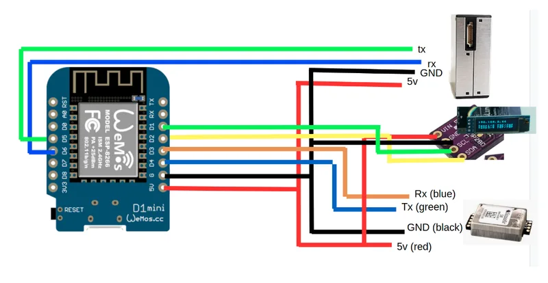
Connecting The PMS5003T Cable Without Connector
In case you cannot solder these small pins, you can also cut and splice the cable and solder it directly onto the PCB just below the JST plug.
Prepare the following four wires as per this image. Please make sure you cut the correct wires.
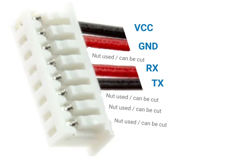
Then solder them into the throughholes names V, G, TX and RX.
NOTE: It can be confusing that the default cable of the PMS has a black cable for VCC as normally VCC uses red color.
Testing And Putting It Into The Enclosure
Now you can power on the device. You need to connect it to the Wi-Fi. To do this open you Wi-Fi settings on the phone and look for a hot spot called "AirGradient______". Then connect to it and enter your Wi-Fi network credentials. It will then connect to Wi-Fi and start displaying and sending the air quality data.
In case you have any issue, check this guide or get help from the Open AirGradient Forum.
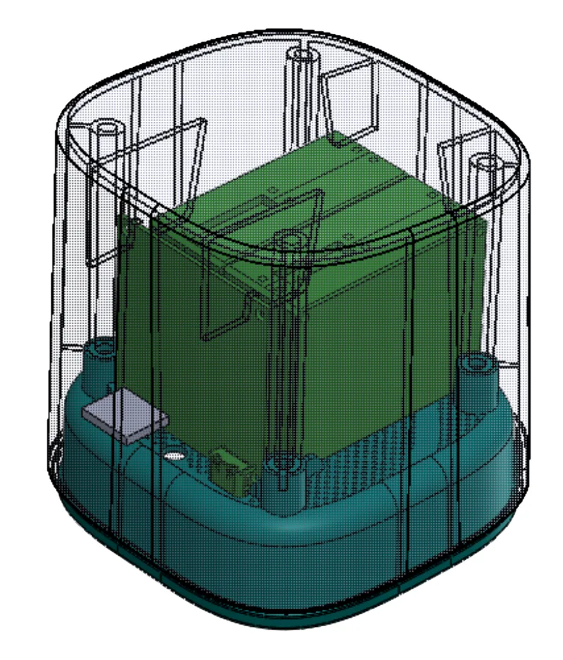
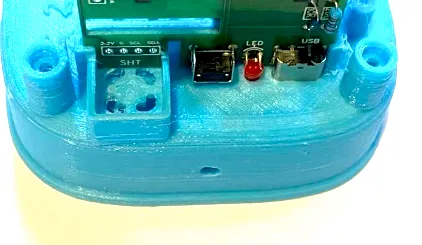
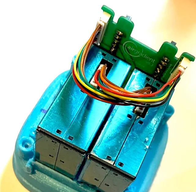
If everything works, you can put the two PMS sensors and the PCB into the enclosure.
Ensure that the LED find the corresponding hole in the enclosure and everything lines up nicely.
When all alligns well, close the enclosure with four screws. Make sure that the PMS cables are towards the middle and do not get in-between the rips of the enclosure.
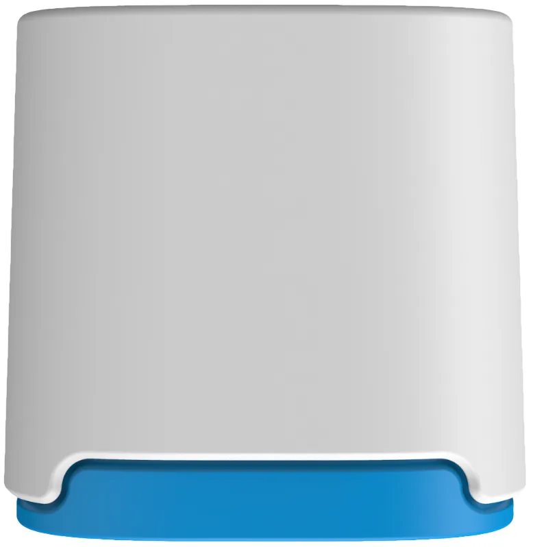
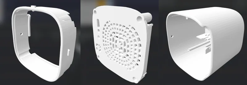
3D Enclosure
You can download STL 3D printer files to print an enclosure that exactly fits the PCB. The 3D enclosure consists of three parts: two parts for the bottom and a bigger top part.
Solutions For Schools
AirGradient offers a sophisticated, powerful and responsive Air Quality Monitoring Solution for Schools. You can connect these DIY monitors to the AirGradient platform, integrate with many existing brands or use our professional AirGradient ONE monitor.
If you are interested in a free trial of the solution for schools, please contact us.
AirGradient Dashboard
Our kits come with several months of free subscription to the AirGradient dashboard. To connect your monitor to the dashboard, please follow these instructions.
CC BY-SA 4.0 Attribution-ShareAlike 4.0 International
This work is licensed under CC BY-SA 4.0.
This license requires that reusers give credit to the creator. If you remix, transform, or build upon the material, you must distribute your contributions under the same license as the original.
Copyright AirGradient Co. Ltd.