The AirGradient DIY Air Quality Sensor (Pro Presoldered-Version, PCB Version 4.2)
The AirGradient DIY Air Quality Sensor (Pro Presoldered-Version, PCB Version 4.2)
Introduction
These build instructions cover the pre-soldered version of the AirGradient Pro monitor kit for PCB version 4.2. If you have a different version please find your correct build instructions in this overview: https://www.airgradient.com/documentation/kb/kb-diy-the-airgradient-builds-overview. The version number is printed on the PCB.
The build instructions of the version that require soldering can be found here.
The AirGradient Pro DIY monitor measures PM2.5, CO2, Temperature and humidity. These measures can be shown on the display and sent to a server (e.g. the AirGradient platform or any other cloud backend) for data logging.
You can purchase the kit with all components from our Online Store and be sure that everything fits. We ship world-wide.
Video Tutorial
Skills And Equipment Required
For this project you should be familiar with the following:
| Skill | Description |
|---|---|
| Computer | A Linux, Mac, or Windows computer with the Arduino IDE installed to flash the software onto the D1 Mini. You can also flash the software directly from the browser. |
| Screwdriver | You need a Torx (T6) screwdriver which is included in the kit. |
Components
Below is the list of components that you will receive with the pre-soldered kit:
| Component | Approx. Price |
|---|---|
| AirGradient Pro PCB | with OLED Display, connectors and pin sockets |
| D1 Mini v4 USB-C | with pre-soldered pins |
| Plantower PMS5003 PM Sensor | with cable |
| Senseair S8 CO2 Sensor | with pre-soldered pins |
| SHT31 / SHT40 Temperature and Humidity Sensor Module | with pre-soldered pins |
| USB-C Cable | 90-degree head |
| Enclosure | UV-resistant injection molded ASA plastic |
| Screws for Enclosure | M1.8x10 (Torx T6) |
| Screws for PCB | M2*4.5 (Torx T6) |
| Screws for PM Sensor | M2*4.5 (Torx t6). Same screws as for PCB. |
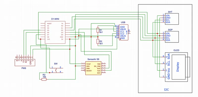
Schematics
Assembly
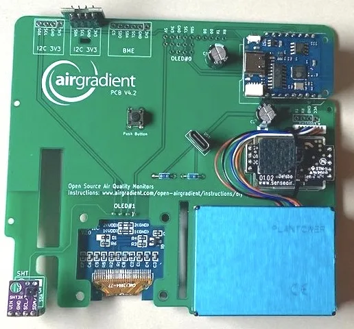
The assembly of the pre-soldered parts is very simple, just make sure you mount the components in the correct direction. The labels on the components should match the labels on the PCB. The PCB might come in green or black color but are functionally identical.
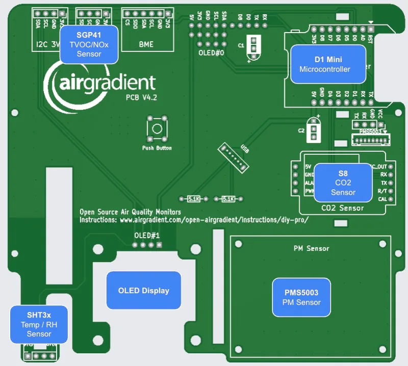
We recommend you start in the following order:
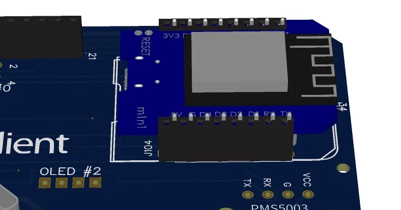
D1 Mini
Put the D1 microcontroller onto the pin sockets labelled "Microcontroller". Make sure that the orientation is correct and all pins slide into the sockets. Ensure that the USB port of the D1 faces inwards and the antenna outwards.
SHT31 / SHT40 Module (Temperature and Humidity)
The kit comes either with an SHT31 or an SHT40 temperature / humidity module. Please check below how to install it.
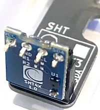
If you have the SHT31 Module, then put it on the pin sockets labelled "SHT". Make sure that the orientation is correct and all pins slide into the sockets as per picture below.
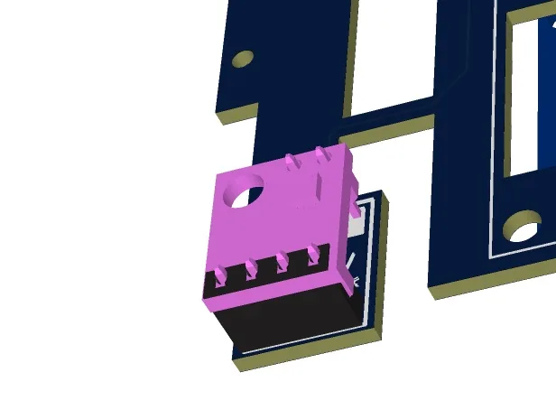
If you have the SHT40 Module with the AirGradient icon on it and the 90 degree pins, then you need to put it into the pin headers forward facing as per the picture below.
Senseair S8 Module (CO2 Sensor)
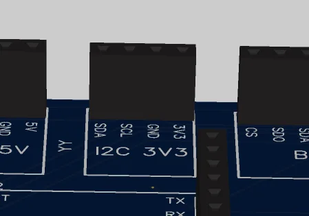
Put the CO2 Module onto the pin sockets labelled "CO2 Sensor". Make sure that the orientation is correct and all pins slide into the sockets.
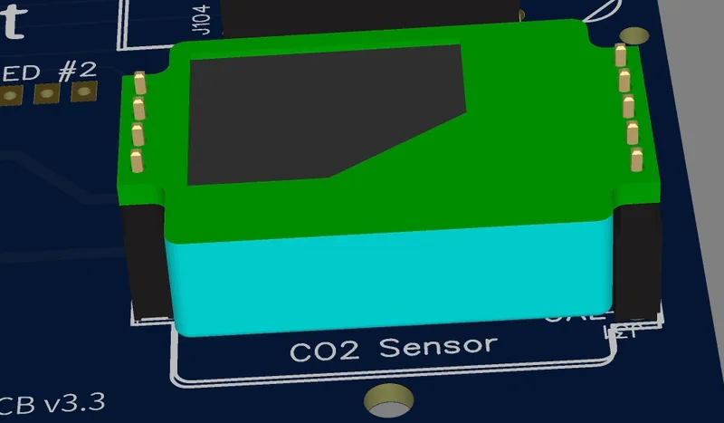
Important: Compared to the smaller DIY Basic kit, the pins here are soldered the opposite way to enhance the accuracy and airflow around the sensor. So in case you have a DIY Basic kit you cannot swap the sensor modules without resoldering the pins to change their orientation.
The CO2 sensor uses a 7 day automatic baseline calibration and thus might need some time to become accurate.
PMS5003 (PMS Sensor)
The PMS Sensor is connected with the enclosed cable to the PCBs JST connector. Please note that in v4.2 of the PCB, we use a shorter cross-over cable. This means that the longer cable in the previous kits will not work as the longer cable is not of cross-over type. You need to press the cables into the PM sensor and connector tightly. Please ensure that the cable is fully plugged in on both ends.
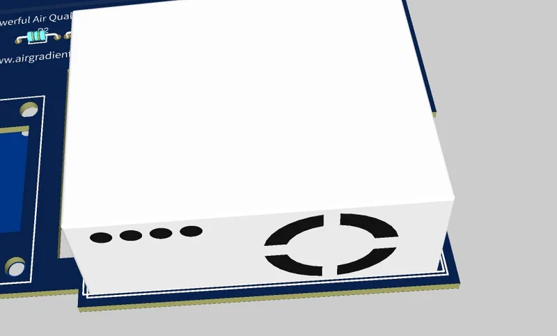
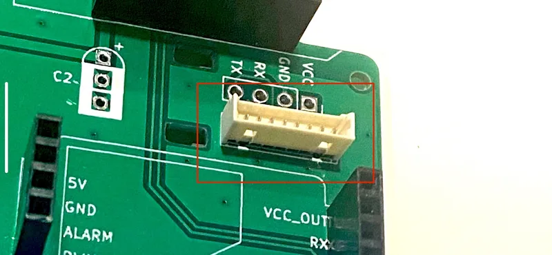

Then screw the PMS5003 onto the PCB.
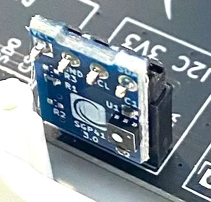
SGP41 AirGradient TVOC / NOx Module
The newer kits now contain the AirGradient TVOC / NOx module by default. Please mount that module on below slot.
Testing And Putting It Into The Enclosure
Now you can power on the device and you should be able to see the display lighting up. If you flashed the Wi-Fi version, you need to connect it to the Wi-Fi. To do this open you Wi-Fi settings on the phone and look for a hot spot called "AirGradient______". Then connect to it and enter your Wi-Fi network credentials. It will then connect to Wi-Fi and start displaying and sending the air quality data.
In case you have any issue, check this guide or get help from the Open AirGradient Forum.
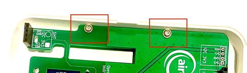
If everything works, you can screw the PCB into the top cover of the enclosure and close the enclosure.
Then screw them on both sides (each 2 screws).
Once the PCB is firmly screwed on the top part of the enclosure, you can close the enclosure with the longer screws.

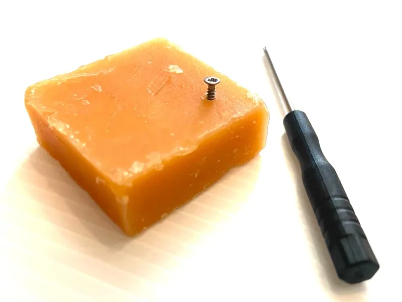
The enclosure screws are going on the four sides into the ventilation vents:
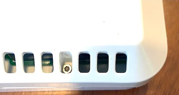
Please note that the mini screwdriver enclosed with the kit might not have enough torque to screw these screws in. In that case, please use a larger T6 screwdriver, or you can also put some oil/soap on the screws to make them go in easier.
Power Supply
The power supply is not included in the kit. Please get a standard 5v, 2A power supply.
Direct Flashing Through The Browser
The pre-soldered kits come with the default AirGradient software already pre-installed but if you want to reflash it, you can follow the instructions below.
You can either manually flash the code through the Arduino software or use the more simple buttons below. If you want to use the Arduino Software, Connect the D1 Mini to your computer through a data-capable cable and press the button below. Make sure you use the Chrome or Edge browsers on your computer for this to work.
| Firmware for PCB Version 4.2+ including code for optional AirGradient SGP41 TVOC / NOx Module |
|
|
Once the code is flashed, it will open a hotspot for 60 seconds to which you can connect and then set your Wi-Fi credentials. By default it will connect to the AirGradient Dashboard. If you want to use another endpoint you can change the code with the manual flashing method below.
If you do not connect it to Wi-Fi within the 60 seconds after startup it will go into the offline mode and show the air quality parameters without sending the data.
Manual Flashing With The Arduino Software
The above direct flashing is the easiest way to get the firmware onto the D1 Mini but if you want to make changes to the code, you can also flash the code through the Arduino software environment. All software for the AirGradient DIY sensor is open source and thus you can make any changes you’d like.
Please read the following blog post on how to install the Arduino software, set up the D1 Mini board and the AirGradient Arduino library.
AirGradient Arduino Software Setup Instructions
Flashing Of The AirGradient Firmware
Once you have the Arduino Software setup for the D1 Mini, you can flash it with the AirGradient firmware.
| Step | Description |
|---|---|
| 1 | Go to Tools, Manage Libraries, and then search for AirGradient and install the AirGradient library. |
| 2 | Once it is installed, go to File, Example, AirGradient and select the DIY_PRO_V4_2 code |
| 3 | Read the instructions on top of the example code and install the additional libraries |
| 4 | Then flash this code the same way you flashed the BLINK example |
Configuration
With the button, you can set the configuration of the display. Press the button on start up and it will enter a menu. Then short press the button until you find the configuration you like. Long press the button to save and reboot.
You can set the unit for PM2.5 (μg/m³ or US AQI), the temperature unit (°C or °F) and also rotate the display (previous versions of the kit had the display on the top left). The following configurations are available:
| Configuration Number | Temperature | PM Unit | Orientation |
|---|---|---|---|
| 1 | °C | ug/m3 | Top Left |
| 2 | °C | US AQI | Top Left |
| 3 | °F | ug/m3 | Top Left |
| 4 | °F | US AQI | Top Left |
| 5 | °C | ug/m3 | Bottom Right |
| 6 | °C | US AQI | Bottom Right |
| 7 | °F | ug/m3 | Bottom Right |
| 8 | °F | US AQI | Bottom Right |
Solutions For Schools
AirGradient offers a sophisticated, powerful and responsive Air Quality Monitoring Solution for Schools. You can connect these DIY monitors to the AirGradient platform, integrate with many existing brands or use our professional AirGradient ONE monitor.
If you are interested in a free trial of the solution for schools, please contact us.
AirGradient Dashboard
The easiest way to start using AirGradient Dashboard with your monitor is our onboarding wizard:
It will first guide you through the account creation (or login if you already have an AirGradient account).
Then you will be able to set up your place.
A place is where you can connect several monitors to. For example your house, school or office. Each place has its own dashboard.
Once you have your account and place setup,
you will be able to connect your monitor to the WiFi and add it to your place’s dashboard by following the wizard instructions.
In case you only want to connect the WiFi or have some problems, please check out our knowledge base articles.
CC BY-SA 4.0 Attribution-ShareAlike 4.0 International
This work is licensed under CC BY-SA 4.0.
This license requires that reusers give credit to the creator. If you remix, transform, or build upon the material, you must distribute your contributions under the same license as the original.
Copyright AirGradient Co. Ltd.