The AirGradient DIY Air Quality Sensor (Pro Version PCB Version 4.2)
The AirGradient DIY Air Quality Sensor (Pro Version PCB Version 4.2)
Please note that these are the instruction for the DIY PRO PCB Version 4.2 that has an improved PCB. If you have a different version please find your correct build instructions in this overview: https://www.airgradient.com/documentation/kb/kb-diy-the-airgradient-builds-overview. The version is printed on the PCB.
Introduction
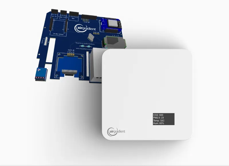
The AirGradient Pro DIY monitor measures PM2.5, CO2, temperature and humidity. These measures can be shown on the display and sent to a server (e.g. the AirGradient platform or any other cloud backend) for data logging.
The AirGradient Pro version has the following advantages compared to the DIY Basic Kit:
- Highly extendable e.g. with a TVOC or barometric pressure sensor, RGB LEDs, etc.
- More accurate measurement for temperature as the enclosure has been designed for enhanced airflow and the temperature sensor is separated from the other components.
- Larger OLED display allowing more information to be displayed.
You can completely build the monitor on your own with the instructions below and open-source code or, optionally you can go to our online shop and purchase it as a kit that includes a professional enclosure. We also offer the kit as a pre-soldered version for a very easy assembly.
Besides below written instructions, you can also watch a YouTube video of the assembly process. Many thanks to @DIYinstruct for making this video!
IMPORTANT: If you have the pre-soldered version, please find your applicable build instruction on our overview page: https://www.airgradient.com/documentation/kb/kb-diy-the-airgradient-builds-overview.
Skills And Equipment Required
For this project you should be familiar with the following:
| Skill | Description |
|---|---|
| Soldering skills | Most of the components we use need soldering. The USB and PMS connectors are small and therefore difficult to solder but these connectors are optional and the monitor can also be built without them. |
| Soldering Iron & Solder | To solder the component pins and cables. |
| Breadboard | A breadboard is helpful to fix the components in place during soldering. |
| Computer | A Linux, Mac, or Windows computer with the Arduino IDE installed to flash the software onto the D1 Mini. You can also flash the software directly from the browser. |
| USB-C Data Cable | A USB-C cable for flashing the microcontroller and later powering it. If you use the enclosure, you need a 90 degree USB-C cable plug. |
In case you are unfamiliar with soldering or want to get the monitoring working as quickly as possible, we also have pre-soldered kits available, which can be assembled in just a few minutes with no soldering needed.
Components
Below is the list of components that you need to source, with a link to AliExpress and typical price ranges. Please note we have no association with the linked sellers and only provide the links as an example of the components, not an endorsement of a seller or a guarantee of the linked product quality.
| Component | Approx. Price |
|---|---|
| Wemos D1 Mini v4 USB-C | USD 4 - 6 |
| 1.3" OLED display | USD 3 - 5 |
| Plantower PMS5003 PM Sensor | USD 15 - 20 |
| Senseair S8 CO2 Sensor | USD 25 - 30 |
| SHT31 Temperature and Humidity Sensor Module | USD 3 - 5 |
| Button | < USD 1 |
| USB-C Connector 6 Pin | < USD 1 |
| JST Connector 1.25mm 8 Pin for PMS | < USD 1 |
| Resistors 5.1KΩ (2x) | < USD 1 |
| Female Pin Headers 4Pin | < USD 1 |
| Female Pin Headers 5Pin | < USD 1 |
| Electrolytic Capacitors 470uF / 16v (2x) | < USD 1 |
| Screws for Enclosure | Enclosure: M1.8x10 (Torx M6) |
| Screws for PCB | M2*4.5 (Torx M6) |
| Screws for PM Sensor | M2*4.5 (Torx M6). Same screws as for PCB. |
| USB-C Cable 90 degrees | USD 3 - 6 |
| PCB | See below on how to make a PCB |
| Enclosure | See below on how to 3D print the enclosure |
| SGP 41 TVOC/NOx Sensor (Optional) | USD 15 (Available in the AirGradient Shop) |
AliExpress might not ship to all countries. In case they do not ship to your country, please try and source the exact same component from elsewhere.
You can also purchase the kit with all required components from our Online Store and be sure that everything fits. We ship world-wide.
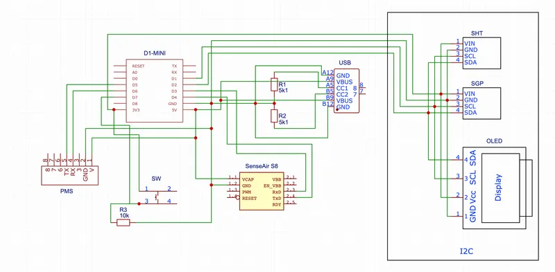
Schematics
You can use the following schematics:
Make Your Own PCBs
In case you want to make your own PCB you can use our Gerber files.
Direct Flashing Through The Browser
You can either manually flash the code through the Arduino software or use the more simple buttons below.
Connect the D1 Mini to your computer through a data-capable cable and press the button below. Make sure you use the Chrome or Edge browsers on your computer for this to work.
| Firmware for PCB Version 4.2 including code for optional AirGradient SGP41 TVOC / NOx Module |
|
|
Once the code is flashed, it will open a hotspot for 90 seconds to which you can connect and then set your Wi-Fi credentials. By default it will connect to the AirGradient Dashboard. If you want to use another endpoint you can change the code with the manual flashing method below.
If you do not connect it to Wi-Fi within the 90 seconds after startup it will go into the offline mode and show the air quality parameters without sending the data.
If you flash with the method above, you can skip the next section and continue at the section "Soldering the Components".
Manual Flashing With The Arduino Software
The above direct flashing is the easiest way to get the firmware onto the D1 Mini but if you want to make changes to the code, you can also flash the code through the Arduino software environment. All software for the AirGradient DIY sensor is open source and thus you can make any changes you’d like.
Please read the following blog post on how to install the Arduino software, set up the D1 Mini board and the AirGradient Arduino library.
AirGradient Arduino Software Setup Instructions
Flashing Of The AirGradient Firmware
Once you have the Arduino Software setup for the D1 Mini, you can flash it with the AirGradient firmware.
| Step | Description |
|---|---|
| 1 | Go to Tools, Manage Libraries, and then search for AirGradient and install the AirGradient library. |
| 2 | Once it is installed, go to File, Example, AirGradient and select the DIY_PRO_V4_2 code |
| 3 | Read the instructions on top of the example code and install the additional libraries |
| 4 | Then flash this code the same way you flashed the BLINK example |
| 5 | Once you have successfully uploaded the code you can continue building the hardware |
Configuration
With the button, you can set the configuration of the display. Press the button on start up and it will enter a menu. Then short press the button until you find the configuration you like. Long press the button to save and reboot.
You can set the unit for PM2.5 (μg/m³ or US AQI), the temperature unit (°C or °F) and also rotate the display (previous versions of the kit had the display on the top left). The following configurations are available:
| Configuration Number | Temperature | PM Unit |
|---|---|---|
| 1 | °C | ug/m3 |
| 2 | °C | US AQI |
| 3 | °F | ug/m3 |
| 4 | °F | US AQI |
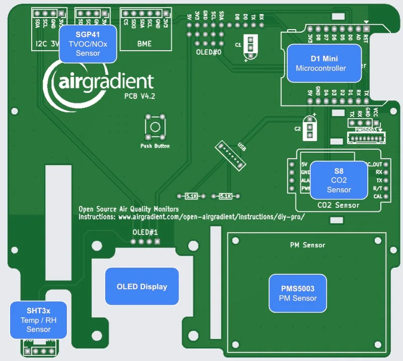
Soldering The Components
Now that you have the firmware flashed, you can solder the components onto the PCB. Make sure you solder the pins in the correct direction. The PCB might come in green or black color but are functionally identical.
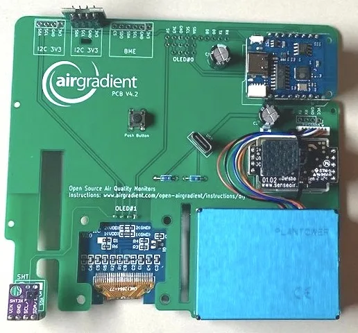
We recommend you start in the following order:
OLED Display Soldering
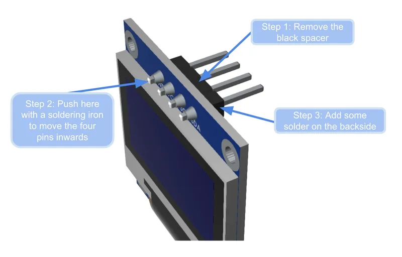
To fit the OLED display perfectly into the enclosure, the pins need to be adjusted because they reach out too far. Please follow these three steps:
- Remove the black spacer with a small screwdriver or with a small pair of pliers (see Step 1 in the figure below)
- Take the hot soldering iron and push the pins inwards so that they do not stand out too much anymore (see Step 2)
- To ensure that the pins still have strong contact with the display, add some solder on the backside around the pins (see Step 3)
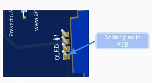
- Put the OLED display through the PCB and mount it into the enclosure. Make sure you tighten all four screws of the PCB. Move the OLED so that it is correctly aligned and use tape to temporarily fix it in place. Most of our enclosures have the display cutout on the bottom right. Make sure you solder the OLED display into the slot called OLED #1 (in case you have an older enclosure with the cutout on the top left, then use the slot called OLED #0).
- From the opposite side, check that the display is properly aligned.
- Solder the display as quickly as possible to prevent damage to the enclosure (melting or deformation from the soldering heat). Put the soldering iron at the lowest temperature that still ensures proper contact. After the soldering is done, immediately use a fan to cool down the solder points as fast as possible.
- Clip off the outstanding pins and carefully remove the tape without damaging the display cable.
D1 Mini Soldering
We recommend to solder all components with pin sockets so that it is easier to replace components or troubleshoot if something does not work.
We use different kind of D1 Mini versions and the one we have made the best experience with is actually called "D1 Mimi" (with "m" instead of "n"). These boards are all compatible and interchangeable.
Important: If you solder the D1 directly on the board, leave enough space between the D1 and the PCB so that you can plug in the USB cable.
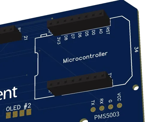
First solder the female pin headers onto the PCB where it says: "Microcontroller".
Then solder the male pins onto the D1 Mini.
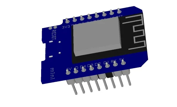
Then you can put the D1 Mini onto the PCB. Make sure that the orientation is correct and that all pins go into the socket. Ensure that the USB port of the D1 faces inwards and the antenna outwards.
Soldering The SHT31 Module (Temperature and Humidity)
To solder the small pins onto the SHT31 module, you can use a breadboard to fix the pins into place. No need to do anything with the two pins on the top of the sensor. Only solder the four pins at the bottom of the module.
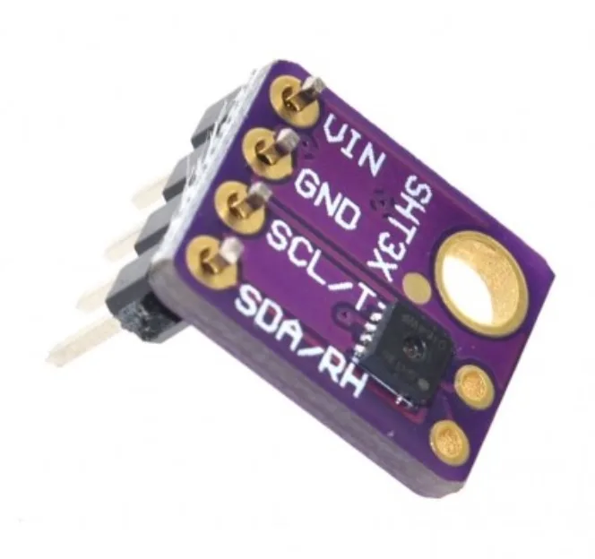
Then solder female pin headers onto the board. The SHT is located at the far isolated corner of the PCB to help ensure accurate temperature measurement.
Then put the SHT31 module onto the pin socket and make sure you have it match the form printed on the PCB. This means that the pins should align the following:
| SHT PCB Label | SHT Module Label |
|---|---|
| 3v3 | VIN |
| GND | GND |
| SCL | SCL |
| SDA | SDA |
Soldering The Senseair S8 Module (CO2 Sensor)
To solder the small pins onto the S8 module, you can use a breadboard to fix the pins into place.
Make sure that the pins face upwards as can be seen on below image.
Important: Compared to the smaller DIY Basic kit, the pins here are soldered the opposite way to enhance the accuracy and airflow around the sensor.
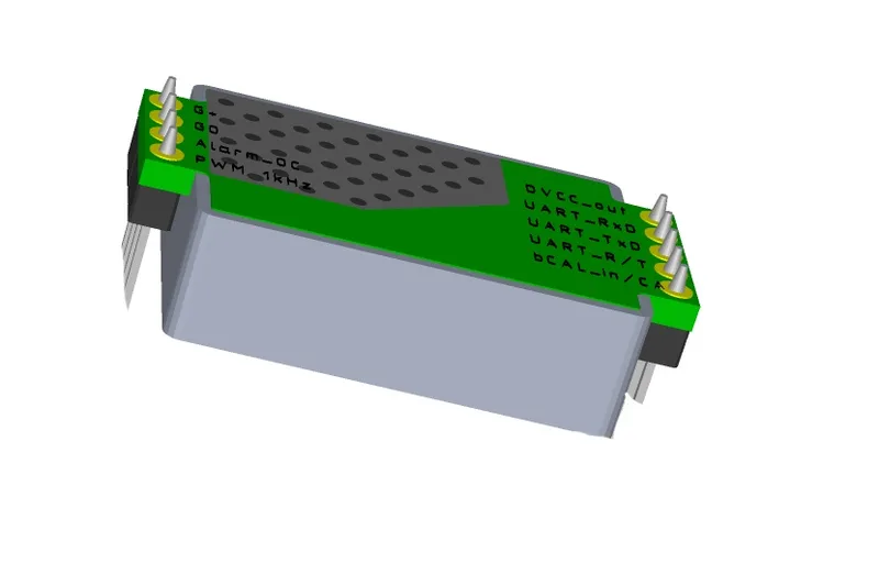
Solder female pin headers onto the PCB. Then put the S8 onto the pin headers.
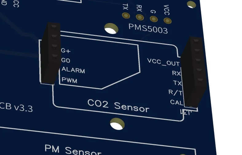
Connecting The PMS5003 (PMS Sensor) Cable
The PMS Sensor is connected with a cable to the PCB.
Please note that from PCB Version 4.2 a smaller cross-over cable is required. The red-black cable often coming with the PMS sensor is not a cross-over cable and it will not work with the JST plug. In case you have the wrong cable, you can splice it and solder it into the through holes provided (see below).
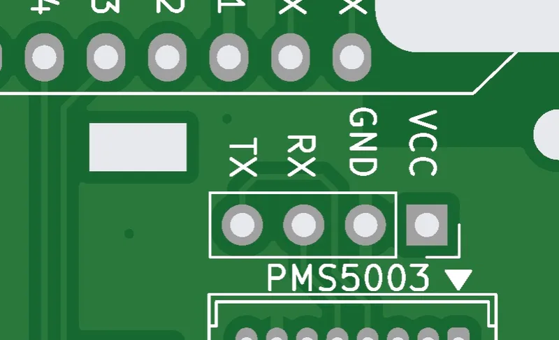
There are two ways to connect it. If you can solder the small JST connector, then solder it on the board:
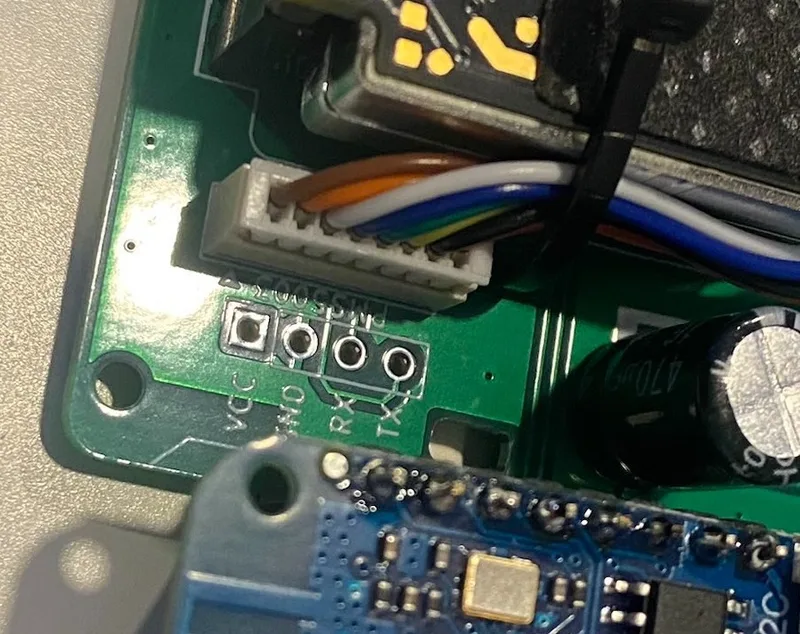
Make sure it is soldered in the correct way (as indicated with the silkscreen and can be seen in the image above).
In case you cannot solder these small pins or do not have a cross-over cable, you can also cut and splice the cable and solder it directly onto the PCB.
Prepare the following four wires as per this image. Please make sure you cut the correct wires.
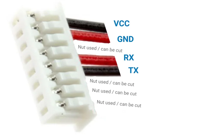
NOTE: It can be confusing that the default cable of the PMS has a black cable for VCC as normally VCC uses red color.
Solder the cable onto the PCB. Please make sure that you solder the correct cable to the correct pin.
After you have soldered the cable onto the PCB, connect the PMS5003 with the other end of the cable.
Then screw the PMS5003 onto the PCB. The PMS modules fan should face the edge of the enclosure so that it can draw in air easily from the outside.
You have two different types of screws in the kit. Use the smaller screws for the PMS sensor and also for screwing the PCB into the enclosure. The larger screws are for closing the two enclosure parts.
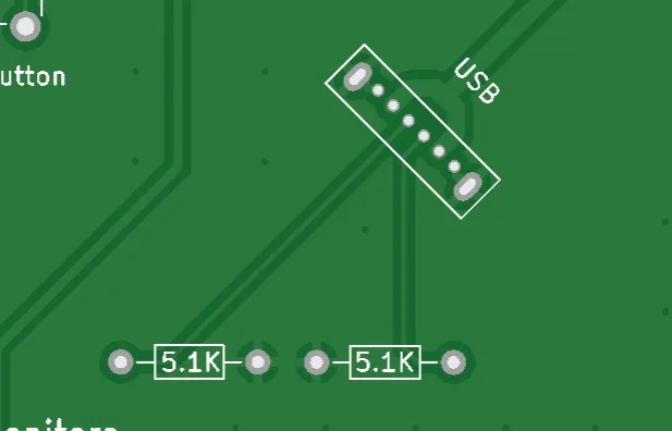
USB-C Connector
If you are confident with soldering the small pads, you can solder the USB-C connector onto the board.
Note that you cannot flash the device through this USB-C port. It only provides power. To flash the D1, you need to connect the cable directly to the MCU.
If you want to use the monitor with smart power adapters (e.g. ones providing a range of voltages), you need to also solder two 5.1k resistors onto the board. If you just want to use a normal 5V power adapter you do not need to do this.
Alternatively, you can use the bigger hole on the back of the enclosure to feed the cable in and connect it directly to the D1. Then you do not need to solder the USB-C connector. Please note that only a straight USB-C cable fits through the hole. So if you get the 90-degree cable from our kit but do NOT want to solder the USB-C connector, you either need to make the hole larger or get a straight USB-C cable.
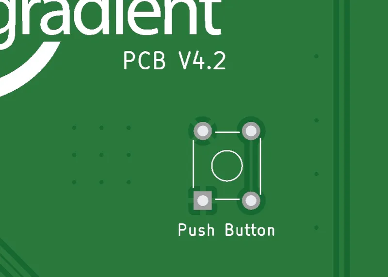
Button
It is important that you solder the button so that you can use our software and are able to switch different configurations (e.g. Fahrenheit, Celcius etc.).
Optional Electrolytic Capacitors
In case you have a low powered power supply, you can optionally add electrolytic capacitors C1 and C2. We recommend 470uF and 16v.
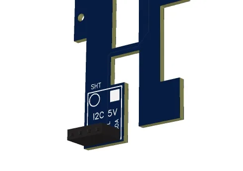
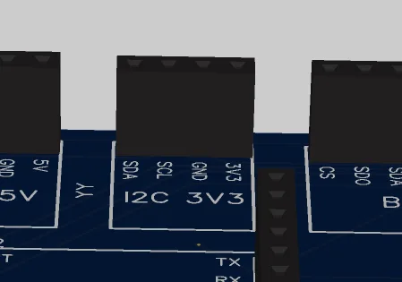
Optional SGP41 AirGradient TVOC / NOx Module
If you purchased the AirGradient TVOC / NOx module, you can solder female pin headers onto one of the top I2C slots and plug the module in there.
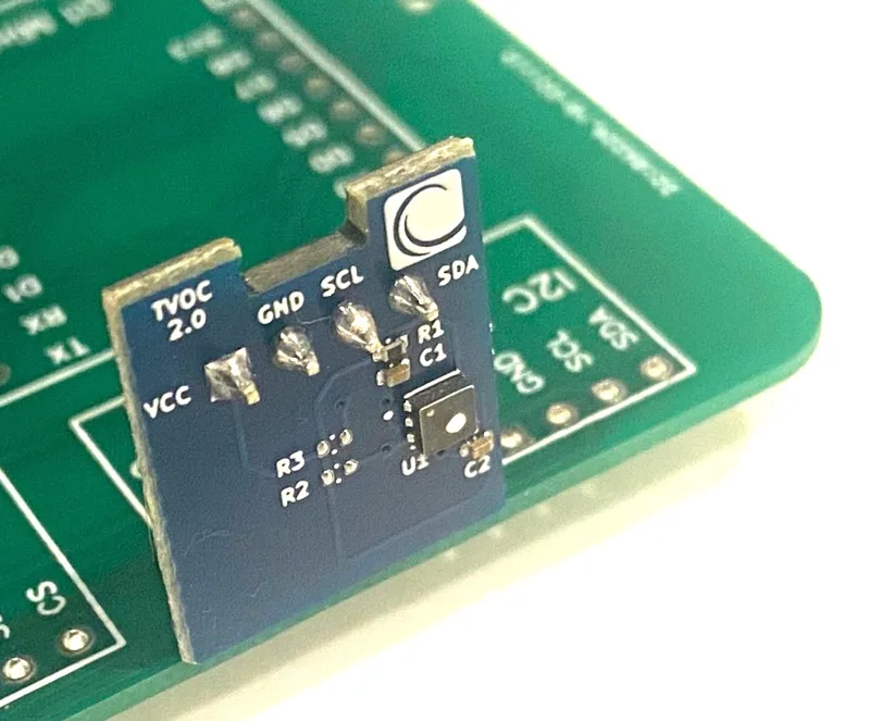
Please note that if you want to use some 3rd party TVOC modules, you might need to remove the pull-up resistors as the I2C bus already has the SHT and OLED module which both already have pull ups. We strongly recommend you use the AirGradient module which does not have pull-up resistors.
Testing And Putting It Into The Enclosure
Now you can power on the device and you should be able to see the display lighting up. If you flashed the Wi-Fi version, you need to connect it to the Wi-Fi. To do this open you Wi-Fi settings on the phone and look for a hot spot called "AirGradient______". Then connect to it and enter your Wi-Fi network credentials. It will then connect to Wi-Fi and start displaying and sending the air quality data.
In case you have any issue, check this guide or get help from the Open AirGradient Forum.
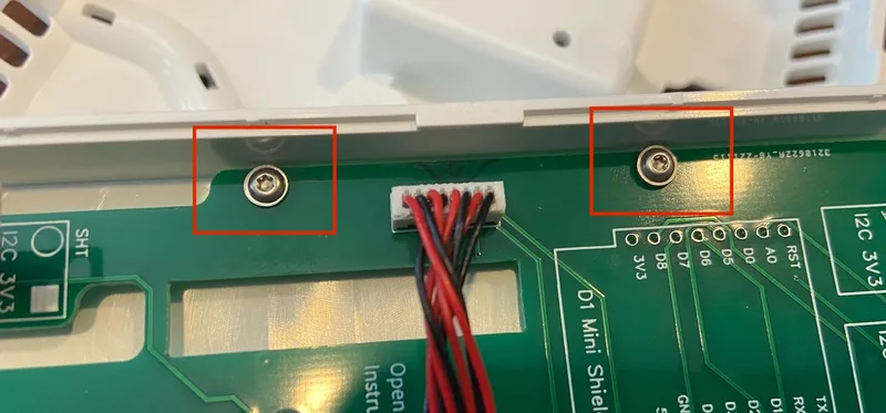
If everything works, you can screw the PCB into the top cover of the enclosure and close the enclosure.

Then screw them on both sides (each 2 screws).
Once the PCB is firmly screwed on the top part of the enclosure, you can close the enclosure with the longer screws.

The enclosure screws are going on the four sides into the ventilation vents:
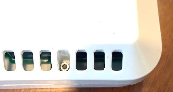
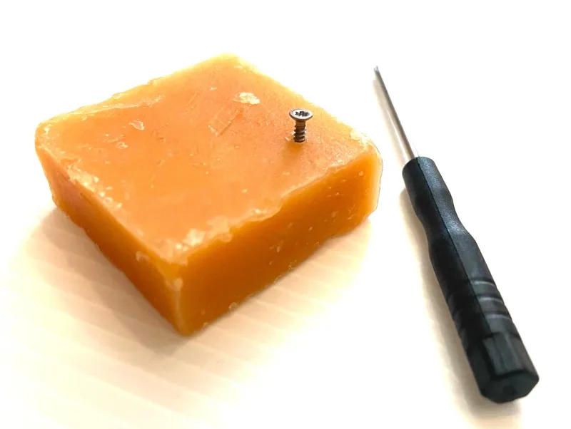
Please note that the mini screwdriver enclosed with the kit might not have enough torque to screw these screws in. In that case, please use a larger T6 screwdriver, or you can also put some oil/soap on the screws to make them go in easier.
Power Supply
The power supply is not included in the kit. Please get a standard 5v, 2A power supply.
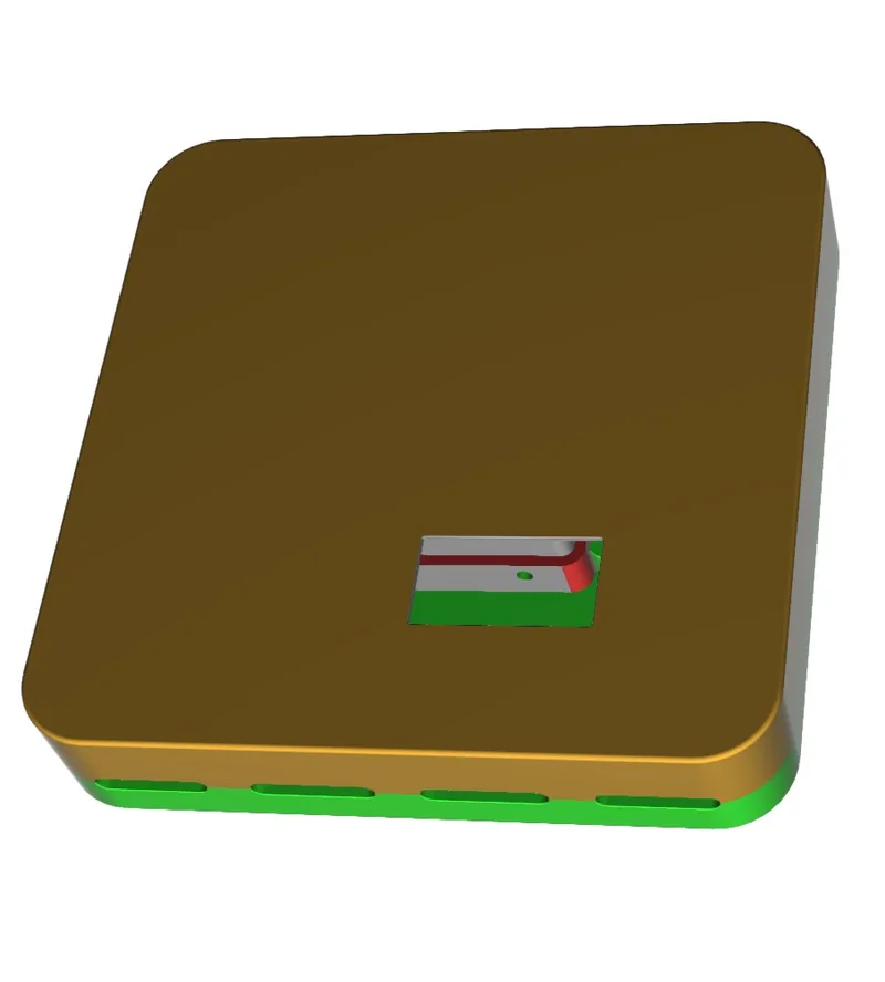
3D Enclosure
You can download STL 3D printer files to print an enclosure that exactly fits the PCB. The 3D enclosure consists of three parts: a top, a bottom and a back cable connection part. The ZIP file also contains the STEP file so that you can make adjustments.
If you do not want to print, our DIY PRO Kit includes a high-quality UV-resistant injection molded plastic enclosure.
Solutions For Schools
AirGradient offers a sophisticated, powerful and responsive Air Quality Monitoring Solution for Schools. You can connect these DIY monitors to the AirGradient platform, integrate with many existing brands or use our professional AirGradient ONE monitor.
If you are interested in a free trial of the solution for schools, please contact us.
AirGradient Dashboard
The easiest way to start using AirGradient Dashboard with your monitor is our onboarding wizard:
It will first guide you through the account creation (or login if you already have an AirGradient account).
Then you will be able to set up your place.
A place is where you can connect several monitors to. For example your house, school or office. Each place has its own dashboard.
Once you have your account and place setup,
you will be able to connect your monitor to the WiFi and add it to your place’s dashboard by following the wizard instructions.
In case you only want to connect the WiFi or have some problems, please check out our knowledge base articles.
CC BY-SA 4.0 Attribution-ShareAlike 4.0 International
This work is licensed under CC BY-SA 4.0.
This license requires that reusers give credit to the creator. If you remix, transform, or build upon the material, you must distribute your contributions under the same license as the original.
Copyright AirGradient Co. Ltd.