These instructions are for the people who ordered our first batch of the new DIY kit with the professional enclsosure. The instruction assume that you have already built a normal AirGradient DIY kit and thus primarily focus on the differences to the default DIY Kit.
Version 1
Important items to note for the hardware built:
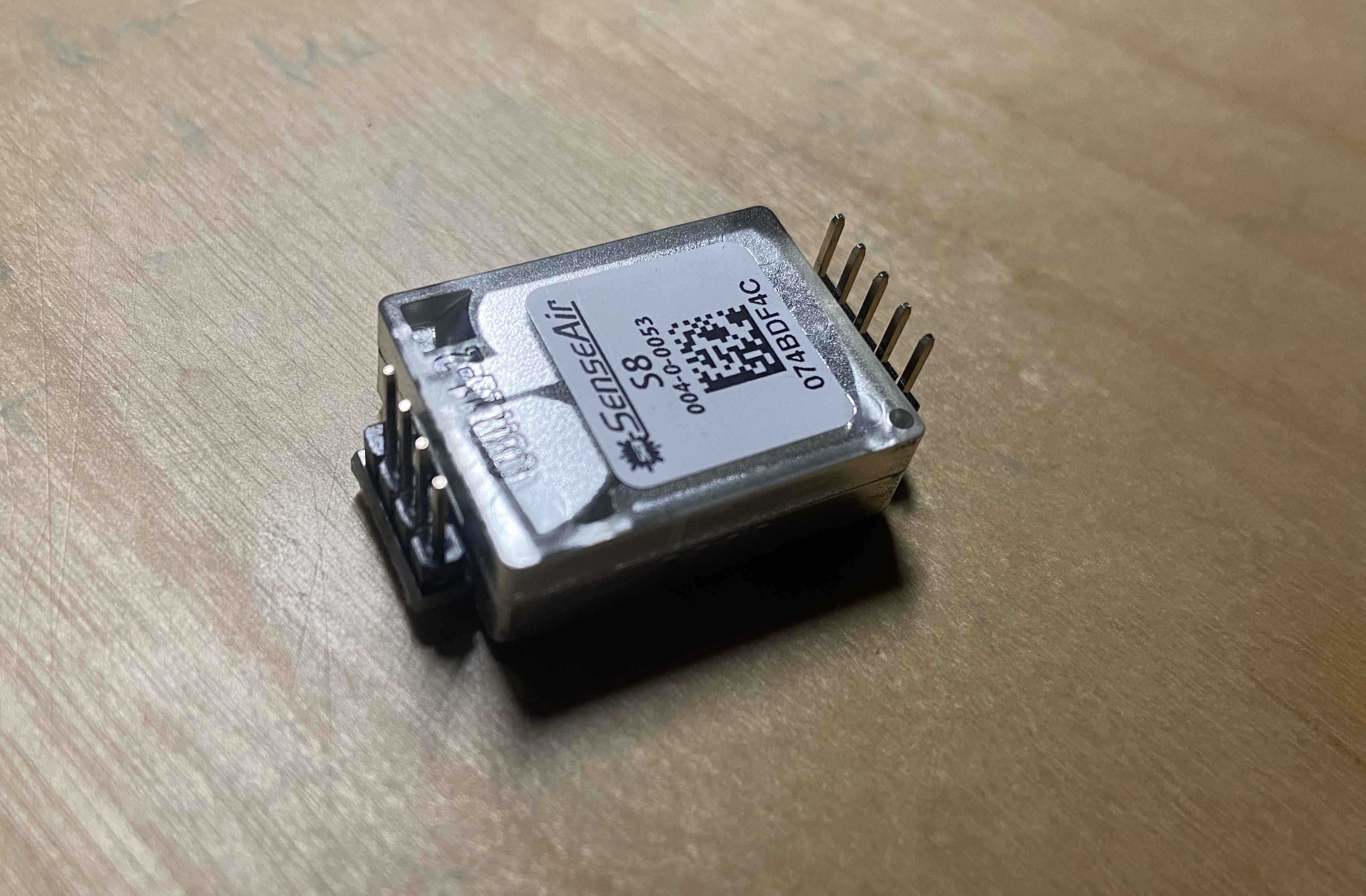
IMPORTANT: CO2 Pins are opposite now:
To comply with the official mounting instructions of the Senseair S8, we have changed the assembly orientation compared to the old DIY kit. So if you use the conversion kit and want to reuse the old S8 module, you need to re-solder the male pins on the opposite side.
It should look like this for the new kit:
S8 module
S8 module assembled on female pin headers on the new PCB.
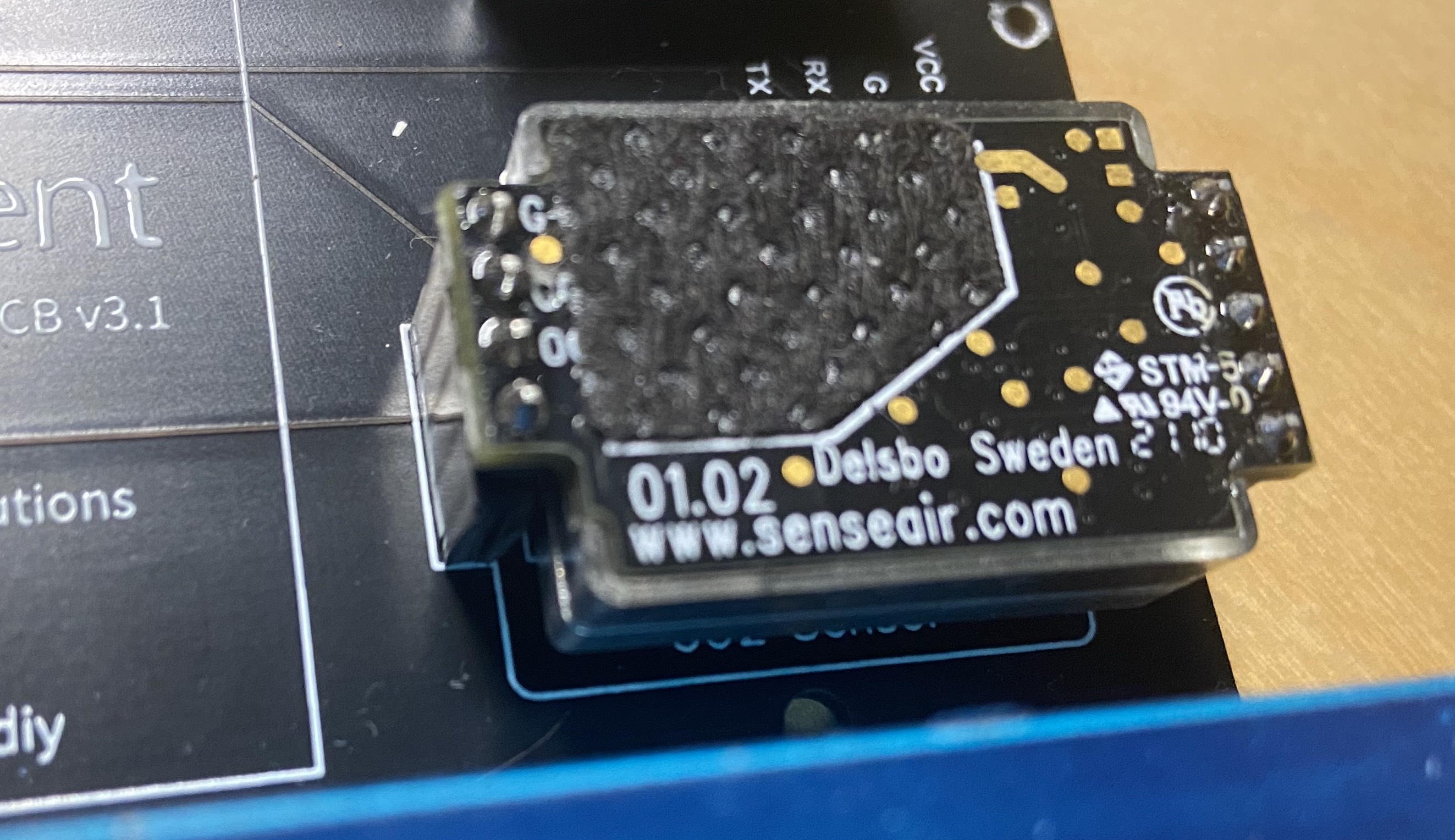
Use female pin headers:
I would recommend that you use female pin headers for all sensors and the Wemos D1 mini. Thus way you can easily remove sensors and components and troubleshoot or repair your sensor much easier. Please also note that with the new pin orientation on the S8 sensor, you can only mount it with the female pin headers.
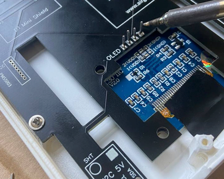
Soldering in the OLED display:
To solder in the OLED display please follow these steps:
- remove the black spacer
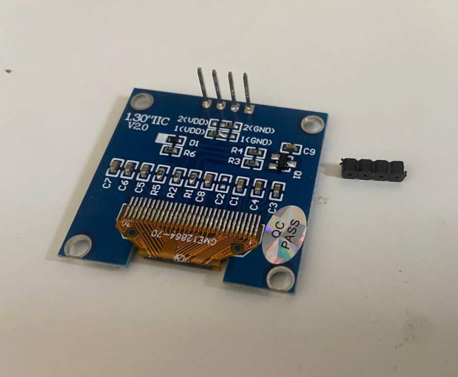
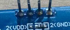
- By default the pins are standing out too much
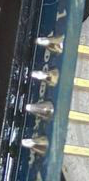
- So we can push them in with a soldering iron
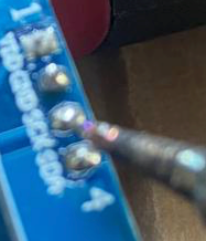
- After pushing in:

- To make good contact, solder on the opposite side
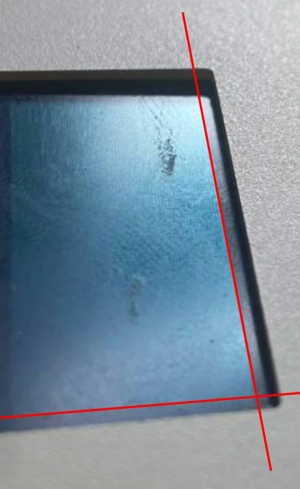
- Put the OLED display through the PCB and mount it into the enclosure. Always use the same enclosure top for the soldering jobs as the soldering might create heat points on the enclosure. Make sure you tight all four screws of the PCB. Move the OLED so that it is correctly aliged and fix it temporarily with a tape
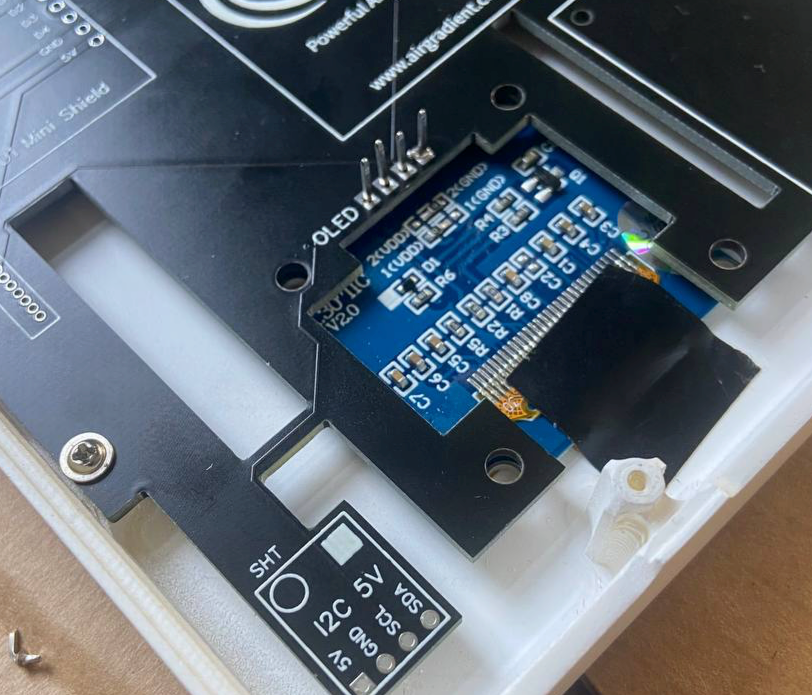
- Check that the display is aligned from the opposite side
- Solder the display in. Please solder as fast as possible to prevent the enclosure opposite of the pins to melt or get melt points. Put solder temperature on the lowest temperature that ensures proper contact. After the soldering done, use a fan to cool down the solder points as fast as possible.
- Clip off the outstanding pins. Carefully remove the tape without damaging the display cable.
PMS Connector
There are two ways to connect the PMS5003 sensors now. You can either do it the same way you connected it in the old kit (cutting the PMS cable and solder it directly on the board) or solder the small JST plug onto the board. If you use the JST plug, please ensure you solder it the correct way.
Other Components
For all other components, there is basically no difference to the previous kit and you can have a look at the instructions for that previous kit.
Libraries needed
You need to install the following libraries from the Arduino library manager:
- AirGradient Library version 1.4.1
- “WifiManager by tzapu, tablatronix” tested with version 2.0.11-beta
- “U8g2” by oliver tested with version 2.32.15
- “SGP30” by Rob Tilaart tested with Version 0.1.5
The Code
Please copy below code into a new Arduino sketch and flash it to the device.
#include <AirGradient.h>
// #include <WiFiManager.h>
#include <ESP8266WiFi.h>
#include <ESP8266HTTPClient.h>
#include <WiFiClient.h>

#include "SGP30.h"
#include <U8g2lib.h>

AirGradient ag = AirGradient();
SGP30 SGP;
U8G2_SH1106_128X64_NONAME_F_HW_I2C u8g2(U8G2_R0, /* reset=*/ U8X8_PIN_NONE);

unsigned long currentMillis = 0;    // stores the value of millis() in each iteration of loop()

const int oledInterval = 5000;
unsigned long previousOled = 0;

const int sendToServerInterval = 10000;
unsigned long previoussendToServer = 0;

const int tvocInterval = 1000; // number of millisecs between TVOC measurements
unsigned long previousTVOC = 0;   // will store last time the TVOC was updated
int TVOC = 0;

const int co2Interval = 5000;
unsigned long previousCo2 = 0;
int Co2 = 0;

const int pm25Interval = 5000;
unsigned long previousPm25 = 0;
int pm25 = 0;

const int tempHumInterval = 2500;
unsigned long previousTempHum = 0;
float temp = 0;
int hum = 0;

String ln1 = "ln1";
String ln2 = "ln1";

String APIROOT = "http://hw.airgradient.com/";

// set to true if you want to connect to wifi. The display will show values only when the sensor has wifi connection
const char* ssid = "xxxx";
const char* password = "xxxxx";


void setup()
{
  Serial.begin(115200);

  u8g2.begin();
  ln2 = String(ESP.getChipId(), HEX);
  updateOLED();

  Serial.println(SGP.begin());
  SGP.GenericReset();

  ag.CO2_Init();
  ag.PMS_Init();
  ag.TMP_RH_Init(0x44);

  WiFi.begin(ssid, password);
  Serial.println("Connecting");
  while(WiFi.status() != WL_CONNECTED) {
    delay(500);
    Serial.print(".");
  }
  Serial.println("");
  Serial.print("Connected to WiFi network with IP Address: ");
  Serial.println(WiFi.localIP());

}


void loop()
{
  currentMillis = millis();
  updateTVOC();
  updateOLED();
  updateCo2();
  updatePm25();
  updateTempHum();
  sendToServer();
}

void updateTVOC()
{
    if (currentMillis - previousTVOC >= tvocInterval) {
      previousTVOC += tvocInterval;
      SGP.measure(true);
      TVOC = SGP.getTVOC();
      Serial.println(String(TVOC));
    }
}

void updateCo2()
{
    if (currentMillis - previousCo2 >= co2Interval) {
      previousCo2 += co2Interval;
      Co2 = ag.getCO2_Raw();
      Serial.println(String(Co2));
    }
}

void updatePm25()
{
    if (currentMillis - previousPm25 >= pm25Interval) {
      previousPm25 += pm25Interval;
      pm25 = ag.getPM2_Raw();
      Serial.println(String(pm25));
    }
}

void updateTempHum()
{
    if (currentMillis - previousTempHum >= tempHumInterval) {
      previousTempHum += tempHumInterval;
      TMP_RH result = ag.periodicFetchData();
      temp = result.t;
      hum = result.rh;
      Serial.println(String(temp));
    }
}

void updateOLED() {
   if (currentMillis - previousOled >= oledInterval) {
     previousOled += oledInterval;
     String ln1 = "CO2:" + String(Co2) + " PM:" + String(pm25);
     String ln2 = "T:" + String(temp) + " H:" + String(hum);
     String ln3 = "TVOC:" + String(TVOC) ;
      char buf[9];
        u8g2.firstPage();
          u8g2.firstPage();
          do {
          u8g2.setFont(u8g2_font_t0_16_tf);
          u8g2.drawStr(1, 10, String(ln1).c_str());
          u8g2.drawStr(1, 30, String(ln2).c_str());
          u8g2.drawStr(1, 50, String(ln3).c_str());
            } while ( u8g2.nextPage() );
   }
}

void sendToServer() {
   if (currentMillis - previoussendToServer >= sendToServerInterval) {
     previoussendToServer += sendToServerInterval;
      String payload = "{\"wifi\":" + String(WiFi.RSSI())
      + ", \"rco2\":" + String(Co2)
      + ", \"pm02\":" + String(pm25)
      + ", \"tvoc\":" + String(TVOC)
      + ", \"atmp\":" + String(temp)
      + ", \"rhum\":" + String(hum)
      + "}";

      if(WiFi.status()== WL_CONNECTED){
        Serial.println(payload);
        String POSTURL = APIROOT + "sensors/airgradient:" + String(ESP.getChipId(), HEX) + "/measures";
        Serial.println(POSTURL);
        WiFiClient client;
        HTTPClient http;
        http.begin(client, POSTURL);
        http.addHeader("content-type", "application/json");
        int httpCode = http.POST(payload);
        String response = http.getString();
        Serial.println(httpCode);
        Serial.println(response);
        http.end();
      }
      else {
        Serial.println("WiFi Disconnected");
      }
   }
}

// Wifi Manager
// void connectToWifi() {
//   WiFiManager wifiManager;
//   //WiFi.disconnect(); //to delete previous saved hotspot
//   String HOTSPOT = "AIRGRADIENT-" + String(ESP.getChipId(), HEX);
//   wifiManager.setTimeout(120);
//   if (!wifiManager.autoConnect((const char * ) HOTSPOT.c_str())) {
//     Serial.println("failed to connect and hit timeout");
//     delay(3000);
//     ESP.restart();
//     delay(5000);
//   }

// }
Need help?
Feel free to reach out to us in case something does not work. In one of the next updates, we will also transfer that code into our AirGradient Arduino library.
Solutions for Schools
AirGradient offers a sophisticated Air Quality Monitoring Solution for Schools. You can connect these Displays to our platform, integrate with many existing brands or use our professional AirGradient sensor.
If you are interested in a free trial, please contact us.
MIT License
The AirGradient DIY sensor’s and display hardware and software is Open Source and licensed under the MIT license. So feel free to use it any way you like! However, we would be happy to hear from you and also appreciate any link back to our page.
Copyright AirGradient Co. Ltd.
Permission is hereby granted, free of charge, to any person obtaining a copy of this software and associated documentation files (the “Software”), to deal in the Software without restriction, including without limitation the rights to use, copy, modify, merge, publish, distribute, sublicense, and/or sell copies of the Software, and to permit persons to whom the Software is furnished to do so, subject to the following conditions:
The above copyright notice and this permission notice shall be included in all copies or substantial portions of the Software.
THE SOFTWARE IS PROVIDED “AS IS”, WITHOUT WARRANTY OF ANY KIND, EXPRESS OR IMPLIED, INCLUDING BUT NOT LIMITED TO THE WARRANTIES OF MERCHANTABILITY, FITNESS FOR A PARTICULAR PURPOSE AND NONINFRINGEMENT. IN NO EVENT SHALL THE AUTHORS OR COPYRIGHT HOLDERS BE LIABLE FOR ANY CLAIM, DAMAGES OR OTHER LIABILITY, WHETHER IN AN ACTION OF CONTRACT, TORT OR OTHERWISE, ARISING FROM, OUT OF OR IN CONNECTION WITH THE SOFTWARE OR THE USE OR OTHER DEALINGS IN THE SOFTWARE.