Knowledge Base
The AirGradient DIY Air Quality Sensor (Basic Version PCB Version 3.0)
Table of Contents
- Introduction and Video
- Skills and Equipment
- Components
- Schematics
- PCBs
- Software
- Soldering the Components
- 3D Enclosure
- Dashboard
- License
Please note that these are the instruction for the DIY BASIC PCB Version 3.0 that mounts the S8 CO2 sensor differently. The version number is written on your PCB. If you have a different version please find your correct build instructions in this overview.
Introduction
As part of the Open AirGradient movement, this instruction teaches you how to build a compact and powerful air quality monitor with AirGradient.
The monitor displays PM2.5, CO2, temperature and humidity and can optionally send the data to the AirGradient platform or any other cloud backend for data logging.
You will need to have good soldering skills. If you lack soldering skills, we also offer the DIY Pro kit as a pre-soldered version for a very easy assembly that can literally be built in 5-10 minutes. More Information about the pre-soldered kit.
If you want to build a monitor with a larger display, a better enclosure and more extensibility, check out the DIY Pro instructions.
Jeff Geerling’s Video Instructions
Jeff featured our DIY Basic kit on his YouTube channel and created a very nice video on how to assemble the monitor.
Skills and Equipment required
For this project you should be familiar with the following:
| Skill | Explanation |
|---|---|
| Soldering skills | The D1 Mini microprocessor and some of the components such as the OLED display need to have the pins soldered onto them. Soldering tutorial.. |
| Soldering iron & Solder | To solder the component pins and cables. |
| Breadboard | A breadboard is helpful to fix the components in place during soldering. |
| Computer | A Linux, Mac, or Windows computer with the Arduino IDE installed to flash the software onto the D1 Mini. |
| USB C Data Cable | To connect the D1 Mini to the computer for flashing and later for electricity. Please make sure you have a USB C cable that not only charges but can also transfer data (for flashing). |
In case you are unfamiliar with soldering or want to get the monitoring working as quickly as possible, we also have pre-soldered kits available, which can be assembled in just a few minutes with no soldering needed.
Components
Below is the list of components that you need to source, with a link to AliExpress and typical price ranges. Please note we have no association with the linked sellers and only provide the links as an example of the components, not an endorsement of a seller or a guarantee of the linked product quality.
| Component | Approx. Price |
|---|---|
| Wemos D1 Mini | USD 2 - 4 |
| Wemos OLED display | USD 2 - 3 |
| Plantower PMS5003 PM Sensor | USD 15 - 20 |
| Senseair S8 CO2 Sensor | USD 25 - 30 |
| SHT30 or SHT31 Temperature and Humidity Sensor Module | USD 3 - 5 |
| PCB | See below on how to make a PCB |
| Enclosure | See below on how to 3D print the enclosure |
AliExpress might not ship to all countries. In case they do not ship to your country, please try and source the exact same component from elsewhere.
You can also purchase the kit from our Online Store. We ship world-wide.
You do not need to put all sensors on the PCB. You can customize your monitor however you like it by removing or adding different sensors.
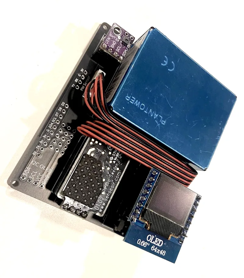
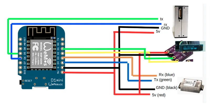
Schematics
You can use the following schematics:
Make Your Own PCBs
In case you want to make your own PCBs you can download the Gerber files from PCB the Easyeda website or order PCBs from there directly. Make sure you download v3 of the PCB drawings.
You can also get the components working without the PCB just by soldering the sensor modules with wires directly to the D1 Mini.
However, we strongly recommend you assemble the monitor with a PCB as it will be much easier and more robust.
Direct Flashing Through The Browser
You can either manually flash the code through the Arduino software or use the more simple button below.
Connect the D1 Mini to your computer through a data-capable cable and press the button below. Make sure you use the Chrome or Edge browsers on your computer for this to work.
Once the code is flashed, it will open a hotspot for 60 seconds to which you can connect and then set your Wi-Fi credentials. By default it will connect to the AirGradient Dashboard. If you want to use another endpoint you can change the code with the manual flashing method below.
If you do not connect it to Wi-Fi within the 60 seconds after startup it will go into the offline mode and show the air quality parameters without sending the data.
| Features | |
|---|---|
| With temperature in Celcius | Your browser doesn't support this. Please use Chrome or Edge on Mac or PC. You are not allowed to use this on HTTP! |
| With temperature in Fahrenheit | Your browser doesn't support this. Please use Chrome or Edge on Mac or PC. You are not allowed to use this on HTTP! |
If you flash with the above method, you can skip the next section and continue at the section "Soldering the Components".
Manual Flashing With The Arduino Software
The above direct flashing is the easiest way to get the firmware onto the D1 Mini but if you want to make changes to the code, you can also flash the code through the Arduino software environment. All software for the AirGradient DIY sensor is open source and thus you can make any changes you’d like.
Please read the following blog post on how to install the Arduino software, set up the D1 Mini board and the AirGradient Arduino library.
AirGradient Arduino Software Setup Instructions
Flashing Of the AirGradient Firmware
Once you have the Arduino software setup for the D1 Mini, you can flash it with the AirGradient firmware.
| Step | Description |
|---|---|
| 1 | Go to Tools, Manage Libraries, and then search for AirGradient and install the AirGradient library. |
| 2 | Once it is installed, go to File, Example, AirGradient and select the DIY_BASIC code |
| 3 | Read the instructions on top of the example code and install the additional libraries |
| 4 | Then flash this code the same way you flashed the BLINK example |
| 5 | Once you have successfully uploaded the code you can continue building the hardware |
Soldering The Components
Now that you have the firmware flashed, you can solder the components onto the PCB. Please make sure you solder the pins in the correct direction. We recommend you start in the following order:
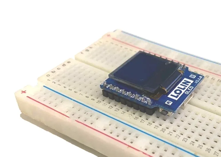
OLED Display Soldering
If you have a breadboard on hand, we recommend that you fix the pins with the breadboard to ensure that they are straight as shown in this picture.
D1 Mini Soldering
Put the long female and male pins through the D1 Mini. Make sure that the female parts are on top of the D1 Mini (on the same side like the USB C plug) as shown in this picture and that the labels of the OLED pins and the D1 mini align:
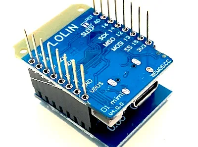
Then connect the freshly soldered OLED display into the female pins to better hold them in place. Then take the D1 Mini with the OLED display attached and turn it around and solder the pins onto the D1 Mini.
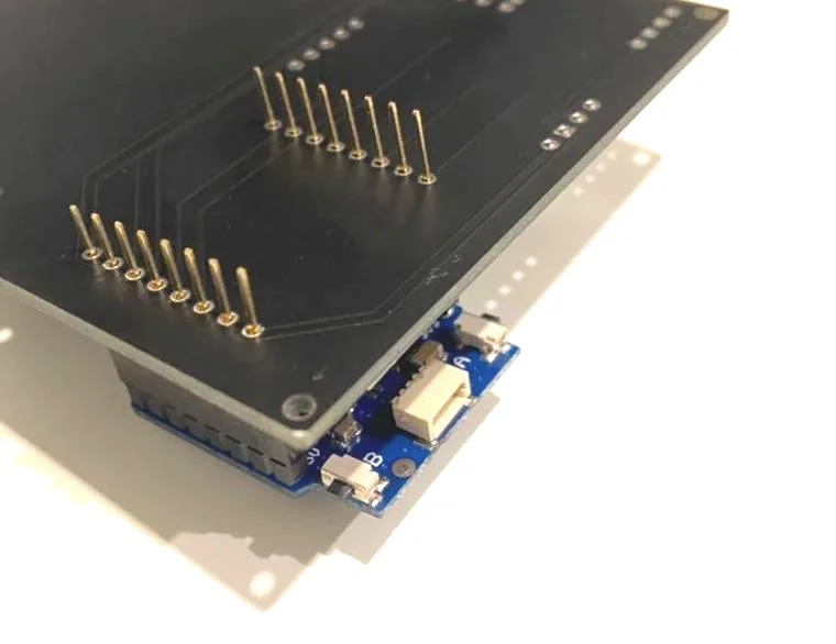
D1 Mini Soldering Onto PCB
The next step is to solder the D1 Mini onto the PCB. Please make sure you solder it the correct way. The USB port needs to face outwards. You can also compare the pin labels on the PCB with the ones on the D1 Mini. You can either solder the D1 Mini directly onto the PCB or use the pin headers as a socket. If you solder it directly, please leave a small gap between the PCB and the D1 Mini to make sure the plug is accessible.
Important: If you use the display or RGB led shield, you need to solder the D1 Mini directly on the PCB without the pin headers as a socket, otherwise it becomes too high and does not fit the enclosure.
Now depending on what sensor modules you want to use, please proceed as below.
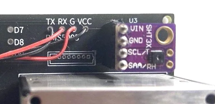
Soldering The Temperature and Humidity Module
The kit might come either with the SHT3x module or the SHT40 module. The modules have a different design, so please follow the instructions below.
Instructions for SHT3x Module
If you have the SHT3x module, you need to first solder the small pins onto the module, you can again use a breadboard to fix it in place. You only need to solder the four pins. No need to do anything with the two pins on the top of the sensor.
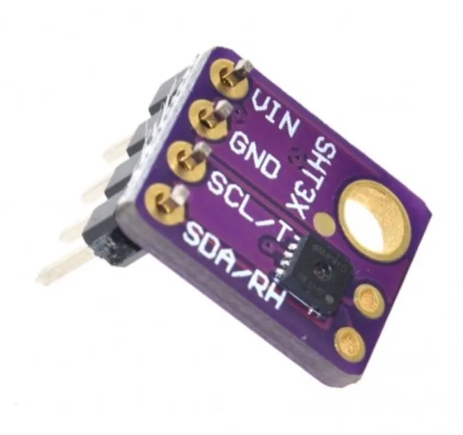
For easier replacement of the sensor modules, solder a 4 pin female header onto the board and then put the SHT3x module onto the pin header as per picture below.
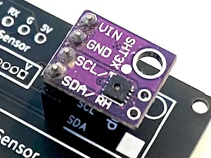
Instructions for SHT40 Module
If you have the SHT40, you do not need to solder pins as the 90 degree pins are already soldered on it but you need to solder a 4 pin female header onto the board and then put the module on it. Please note that when you put the SHT40 module onto the pin headers it needs to face backwards as per the image below.
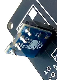
Soldering The Senseair S8 Module (CO2 Sensor)
Solder female pin headers onto the S8 PCB. Then put the S8 onto the pin headers.
Please make sure that the pins face as can be seen on this image. If you purchase the kit from us, these pins are already soldered on.
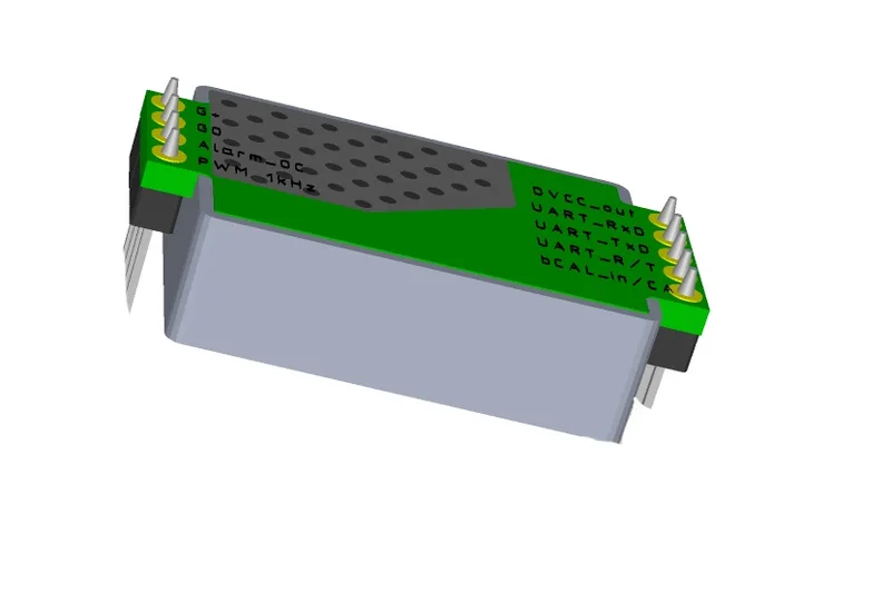
Please note that in previous versions of this PCB, the pins were soldered in the opposite way.
You can use ZIP ties to fix the S8 into place.
Soldering The PMS5003 Module (PMS Sensor)
The PMS Sensor is connected with a cable to the PCB. There are two ways to connect it. If you can solder the small JST connector, then solder it on the board:
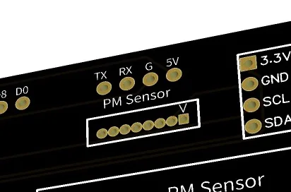
Make sure it is soldered in the correct way (as indicated with the silkscreen and can be seen in the image above).
In case you cannot solder these small pins, you can also cut and splice the cable and solder it directly onto the PCB.
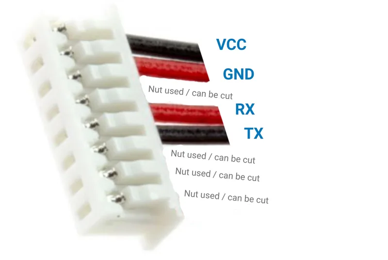
Then solder the cable onto the PCB. Make sure that you solder the correct cable to the correct pin.
After you have soldered the cable or connector to the PCB, connect the PMS5003 with the other end of the cable. Then screw the PMS5003 onto the PCB or use a double sided tape to fix it in place.
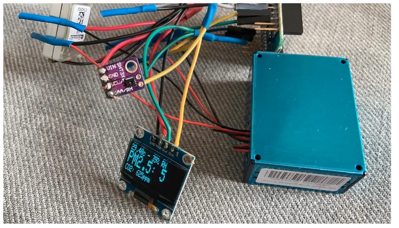
Done & Enjoy
That's all and you can now connect the D1 Mini to power and you should be able to see the display lighting up. If you flashed the Wi-Fi version, you need to connect the D1 Mini to the Wi-Fi. To do this, open the Wi-Fi Settings on your phone and look for a hot spot called "AirGradient-______". Connect to it and enter your Wi-Fi network credentials. It will then connect to your Wi-Fi and start displaying and sending the air quality data.
If there are any issues, you can double check this tutorial and also the images. If you still have problems, please feel free and get in touch with us!
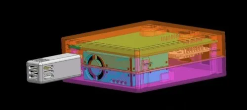
3D Enclosure And Mount
You can download STL 3D printer files to print an enclosure that exactly fits the PCB. The 3D enclosure consists of a top and bottom part. There are two different top parts depending on if you use the OLED display or not. Please note that if you use the OLED you need to solder the D1 Mini directly on the PCB as it otherwise sit too high and not fit the enclosure.
You can also print a small temperature probe that can be snapped onto the enclosure. By thus moving the temperature sensor outside the main enclosure, you can achieve more accurate temperature readings by minimizing the impact of the heat that builds up within the main enclosure.
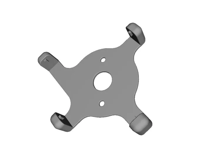
We also have a wall mount available that clicks into the vents of above enclosure and makes it easier to mount it on the wall.
Solutions For Schools
AirGradient offers a sophisticated, powerful and responsive Air Quality Monitoring Solution for Schools. You can connect these DIY monitors to the AirGradient platform, and integrate with many existing brands or use our professional AirGradient ONE monitor.
If you are interested in a free trial of the solution for schools, please contact us.
AirGradient Dashboard
Our kits come with several months of free subscription to the AirGradient dashboard. To connect your monitor to the dashboard, please follow these instructions.
CC BY-SA 4.0 Attribution-ShareAlike 4.0 International
This work is licensed under CC BY-SA 4.0.
This license requires that reusers give credit to the creator. If you remix, transform, or build upon the material, you must distribute your contributions under the same license as the original.
Copyright AirGradient Co. Ltd.