AirGradient Open Air Outdoor Air Quality Monitor (O-1PST) Assembly Instructions
AirGradient Open Air Outdoor Air Quality Monitor (O-1PST) Assembly Instructions
Introduction
Welcome to your AirGradient Open Air!
Our DIY kits are designed for anyone to assemble with no electronics background or soldering experience required. Everything you need comes neatly packed in the box, including a Torx T6 screwdriver. From opening the box to a fully functioning air quality monitor takes roughly 15 minutes.
The PM sensor is pre-mounted, and firmware is pre-installed, so your device will automatically update itself once it connects to Wi-Fi.
If you’re new to AirGradient or air quality monitoring, you’re in the right place. This guide walks you step-by-step through the assembly, connection, and troubleshooting process with pictures and video links along the way.
If you have a different version please find all of our build instructions in this overview: https://www.airgradient.com/documentation/kb/kb-diy-the-airgradient-builds-overview The version number is printed on the PCB under the AirGradient logo. PCB layout references including CAD, Gerber files and more technical details can be found in the same overview.
Video Tutorial
In case you have any problems after completing the build, you can check the troubleshooting section at the end of the article.
Equipment Required
- Torx T6 Screwdriver: Included in the kit. No soldering is required.
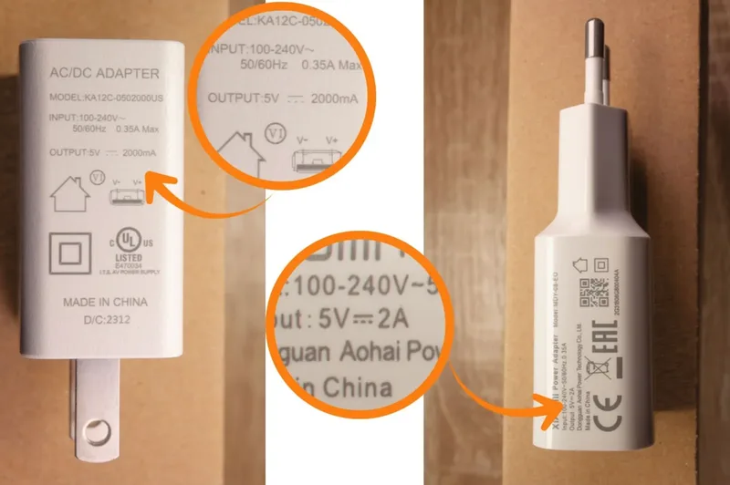
- Power Supply: A standard 5V, 2A USB power supply is required (not included). For outdoor use, you may need to ensure the adapter is weather-rated if it is going to be exposed to the elements.
- Soap: for lubricating screws (optional but recommended).
Components
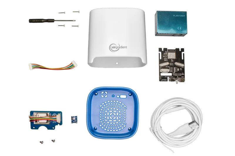
Below is the list of components included in the pre-soldered O-1PST kit:
| Component | Details |
|---|---|
| AirGradient Open Air PCB | With ESP32-C3 microcontroller, connectors and pin sockets |
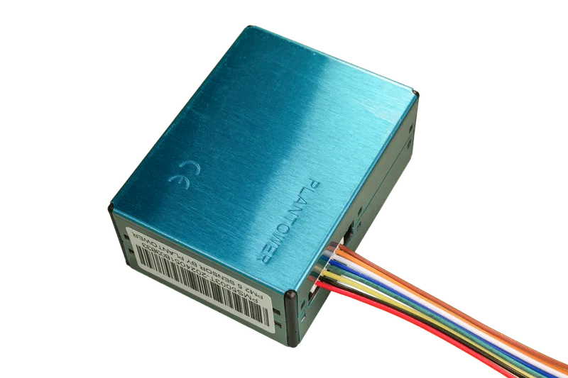
| Plantower PMS5003T PM Sensor | Pre-mounted particulate matter (PM) sensor with cable |
| SenseAir S8/S88 module | NDIR CO2 Sensor with pre-soldered pins |
| SGP41 TVOC / NOx Sensor module | TVOC/NOx Sensor with pre-soldered pins |
| 2x JST Cables | Cross-over cables for PM and CO2 sensors |
| USB-C Cable | 4 meters long (for power and flashing) |
| Enclosure | UV-resistant injection molded ASA plastic |
| Screws (Small) | 2x M1.8x11 for SenseAir S8 module |
| Screws (Large) | 4x M1.8x11 for enclosure closure |
Assembly Instructions
We recommend that you assemble your monitor in the following order:
1. Install the SGP41 Module (TVOC/NOx Sensor)
Plug the SGP41 module into the pin holder on the PCB. Ensure the module faces outwards.
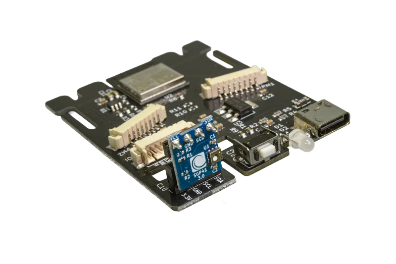
Note: A small gap between the socket and the module is normal and does not affect performance.
2. SenseAir S8/S88 Module (CO2 Sensor)
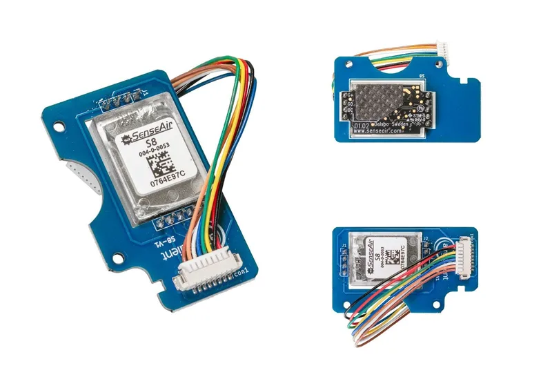
The longer JST cable comes connected to the S8 module. Secure the module to the PCB using the two smaller M1.8x11 screws supplied.
3. Connect the PM Sensor
Connect the shorter JST cable to the Plantower PM sensor. Ensure the connector is seated firmly and in the correct orientation.
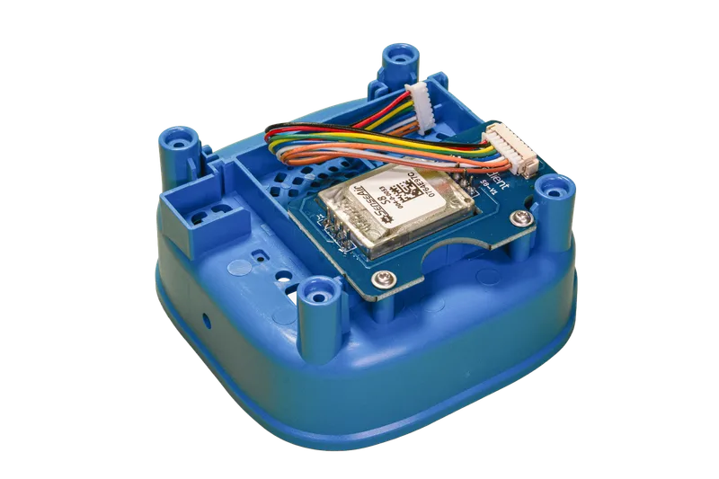
4. PCB Placement and Internal Wiring
Connect the other ends of the cables to the main board:
PM Sensor: Connect to the header labelled "PM1".
CO2 Sensor: Connect to the header labelled "PM2".
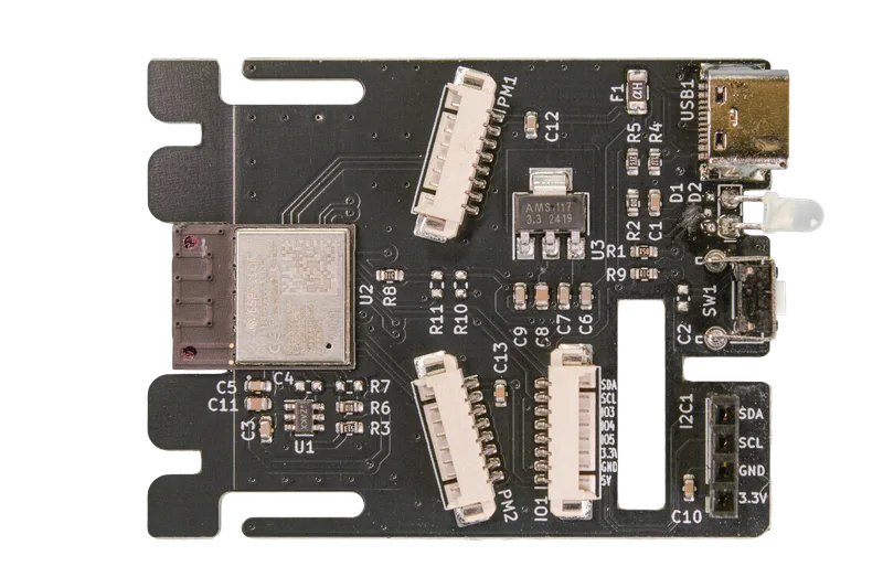
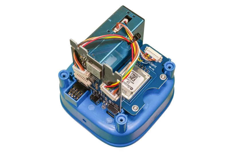
Feed the cables through the dedicated feeder holes on the side of the PCB to keep the internal space tidy. Place the PM sensor and PCB into the bottom part of the enclosure.
The fully assembled PCB will look like below:
5. Take Note of Your PM Module Serial Number
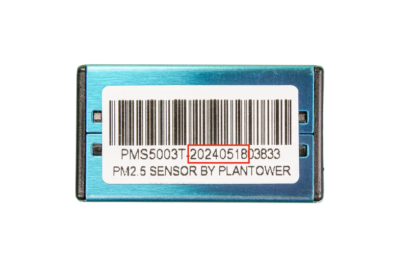
We have developed a range of batch-corrections for the PM sensors used in our monitors which help to improve accuracy and precision. To apply these batch corrections, you will need to know the first eight digits of the PM sensor's serial number.
To find the serial number, please look at the blue PM module. Each sensor will have a sticker like the image above. For further information on the batch corrections, please refer to this article.
To avoid needing to open the monitor at a later date, please note down or take a photo of this number.
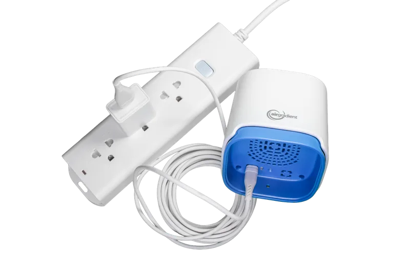
6. Testing the PCB
You can now power on the device by plugging in the USB cable. After a few seconds, you should see the LED on the bottom part light up. The power adapter is not included in the kit. Please use a standard 5V, 2A power supply.
You will likely have one of these lying around your house from a smartphone or another device.
Please note that if the device does not turn on - or if you notice unexpected behaviour like the device restarting randomly - you may need to use a different USB adapter.
7. Connecting Your Device To the Wi-Fi and Closing the Enclosure
To connect the device to WiFi and register it on the AirGradient dashboard, follow the onboarding process.
If you don’t want to use the AirGradient Dashboard use the instructions here: WiFi Connection Instructions. (Video Instructions: Android - iOS)
If everything works, close the enclosure by carefully sliding the top part of the enclosure onto the bottom part with the PCB.
If you feel there is some resistance from components or cables inside the enclosure, do not force it but lift up the top part and check again if the PCB is upright and the cables do not interfere with the plastic rifts.
Once the two parts slide together smoothly, turn the complete assembly around and use the four longer screws to put it together.
Please note that the mini screwdriver enclosed with the kit might not have enough torque to screw these screws all the way in. In that case, please use a larger T6 screwdriver, or you can also put some oil/soap on the screws to make them go in easier.

Please also be careful not to force the screws in, as this can lead to them getting stuck in the case and may make the device hard to open for maintenance.
Power Supply
The Open Air requires a 5V 2A power supply. Because this is an outdoor unit, please ensure your power source is safe for outdoor environments. Using lower-rated power adapters can cause issues.
Firmware Flashing Through The Browser
Your device comes pre-installed with firmware. To update or flash manually: The device comes with pre-installed firmware so it’s ready to run, however, if you want to perform manual firmware updates you do so using this page: AirGradient Firmware Versions
Home Assistant and Local Server
The firmware has native Home Assistant support and should get auto discovered. Additionally, there is a local server exposed that can be used to read data directly from the monitor in a local network (and set configuration parameters).
Troubleshooting
| Behavior | Potential Reason | Fix |
|---|---|---|
| No CO2/PM/TVOC Readings | Sensor module not connected properly | Make sure that the sensors are plugged in correctly and that the cable is firmly connected |
| Enclosure won't close | Cable interference | Re-route cables through the PCB feeder holes and ensure the PCB is perfectly vertical |
| Device not powering on | Insufficient Amperage | Ensure your power adapter provides at least 2A |
Mounting Instructions
For accurate outdoor readings, the device must be mounted correctly to allow airflow while protecting it from direct rain. Please follow the Mounting Guide.
CC BY-SA 4.0 Attribution-ShareAlike 4.0 International
This work is licensed under CC BY-SA 4.0.
This license requires that reusers give credit to the creator. If you remix, transform, or build upon the material, you must distribute your contributions under the same license as the original.
Copyright AirGradient Co. Ltd.